Kia Sportage: Brake Line
Components and Components Location
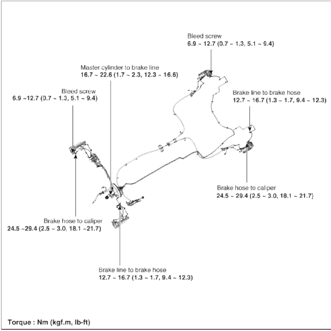
Components
Repair procedures
Removal
1. Disconnect the brake fluid level switch connector, and remove the reservoir cap.
2. Remove the brake fluid from the master cylinder reservoir with a syringe.
CAUTION
Do not spill brake fluid on the vehicle, it may damage the paint; if brake fluid does contact the paint, wash it off immediately with water.
3. Remove the wheel & tire.
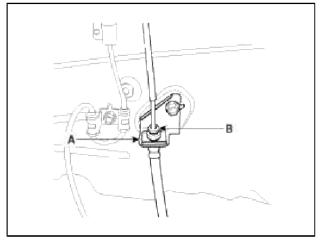
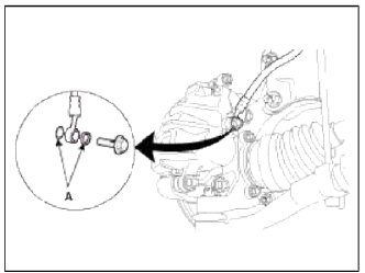
4. Remove the brake hose clip (A).
Front
Rear
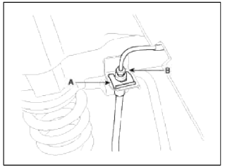
5. Disconnect the brake tube by loosening the tube flare nut (B).
Tightening torque: 12.7 ~ 16.7 N.m (1.3 ~ 1.7 kgf.m, 9.4 ~ 12.3 lb-ft)
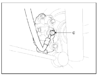
6. Disconnect the brake hose from the brake caliper by loosening the bolt (C).
Tightening torque: 24.5 ~ 29.4 N.m (2.5 ~ 3.0 kgf.m, 18.1 ~ 21.7 lb-ft)
Front
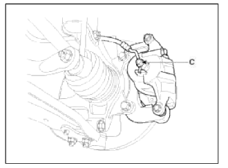
Rear
Inspection
1. Check the brake tubes for cracks, crimps and corrosion.
2. Check the brake hoses for cracks, damage and fluid leakage.
3. Check the brake tube flare nuts for damage and fluid leakage.
4. Check brake hose mounting bracket for crack or deformation.
Installation
1. Installation is the reverse of removal.
CAUTION
Use a new washer (A) whenever installing.
2. After installation, bleed the brake system. (Refer to Brake system bleeding)
3. Check the spilled brake oil.
READ NEXT:
 Brake Pedal
Components and Components Location
Components
Cowl bracket
Brake pedal member assembly
Stop lamp switch
Return spring
Brake pedal stopper
Clevis pin
Snap pin
Brake pedal
Front Disc Brake
Components and Components Location
Components
Guide rod bolt
Bleed screw
Caliper bracket
Caliper body
Inner pad shim
Brake pad
Pad retainer
Repair procedures
Removal
1. R
Rear Disc Brake
Components and Components Location
Components
Guide rod bolt
Bleed screw
Caliper bracket
Caliper body
Inner pad shim
Brake pad
Pad retainer
Repair procedures
Removal
1. R
SEE MORE:
Assembly
Measuring dimensions before welding
When assembling a new part, assemble it according to the body dimensions
given in Section 31, and start welding
after checking the gaps with nearby parts.
Caution when welding
The number of welding points should be determined based on the criteria
below:
With the smart key
Door locks
Know how to use the door lock so that
you can lock or unlock the door if necessary.
With the smart key
Carrying the smart key, you may
lock
and unlock the vehicle doors (and liftgate).
Also, you may start the engine.
Refer to the following for more details.
Locking
Pressing
Content
- Home
- Kia Sportage - Fifth generation (NQ5) - (2022-2026) - Owner's Manual
- Kia Sportage - Second generation (JEKM) (2005-2015) - Body Workshop Manual
- Kia Sportage Third generation (SL) - (2011-2016) - Service and Repair Manual
- Sitemap
- Top articles
