Kia Sportage: Rear Disc Brake
Components and Components Location
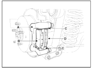
Components
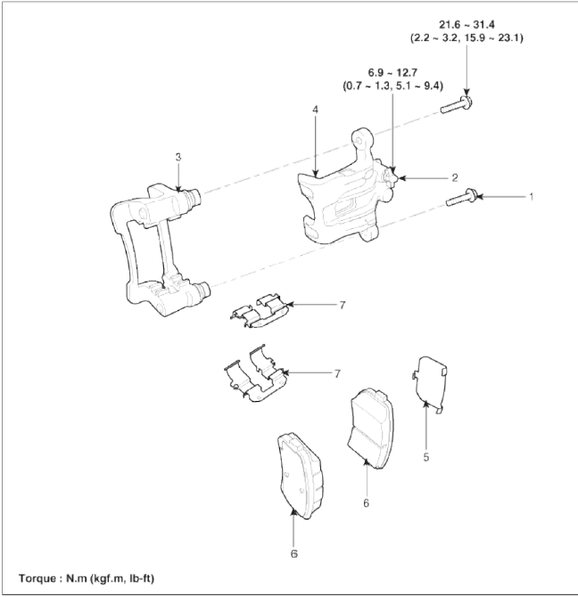
- Guide rod bolt
- Bleed screw
- Caliper bracket
- Caliper body
- Inner pad shim
- Brake pad
- Pad retainer
Repair procedures
Removal
1. Remove the rear wheel & tire.
Tightening torque: 88.3 ~ 107.9 N.m (9.0 ~ 11.0 kgf.m, 65.1 ~ 79.6 lb-ft)
2. Remove the rear shock absorber (A). [2WD Only]
(Refer to the Suspension group - rear shock absorber)
![3. Remove the rear upper arm (B). [2WD) Only]](images/books/1921/14/index%2070.png)
3. Remove the rear upper arm (B). [2WD) Only]
(Refer to the Suspension group - rear upper arm)
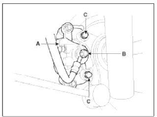
4. Loosen the hose eyebolt (B) and caliper mounting bolts (C), then remove the rear caliper assembly (A).
Tightening torque:
Brake hose to caliper (B): 24.5 ~ 29.4 N.m (2.5 ~ 3.0 kgf.m, 18.1 ~ 21.7 lb-ft)
Caliper assembly to carrier (C): 78.5 ~ 98.1 N.m (8.0 ~ 10.0 kgf.m, 57.9 ~ 72.3 lb-ft)
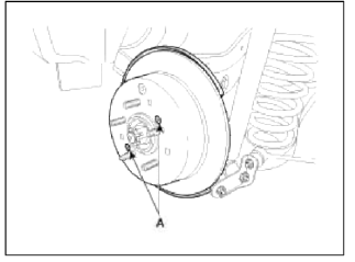
5. Remove the rear brake disc by loosening the screws (A).
Replacement
Rear brake pads
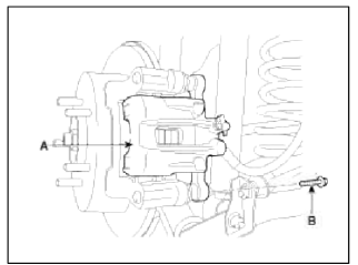
1. Loosen the guide rod bolt (B) and pivot the caliper (A) up out of the way.
Tightening torque: 21.6 ~ 31.4 N.m (2.2 ~ 3.2 kgf.m, 15.9 ~ 23.1 lb-ft)
2. Replace pad shim (D), pad retainers (C) and brake pads (B) in the caliper bracket (A).
Inspection
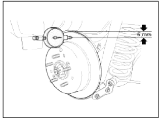
Rear Brake Disc Thickness Check
1. Check the brake pads for wear and fade.
2. Check the brake disc for damage and cracks.
3. Remove all rust and contamination from the surface, and measure the disc thickness at 8 points, at least, of same distance (5mm) from the brake disc outer circle.
Brake disc thickness
Standard: 10 mm (0.39 in)
Service limit: 8.4 mm (0.33 in)
Deviation: less than 0.005 mm (0.0002 in)
4. If wear exceeds the limit, replace the discs and pad assembly left and right of the vehicle.
Rear Brake Pad Check
1. Check the pad wear. Measure the pad thickness and replace it, if it is less than the specified value.
Pad thickness
Standard value: 10 mm (0.393 in)
Service limit: 2.0 mm (0.0787 in)
2. Check that grease is applied, to sliding contact points and the pad and backing metal for damage.
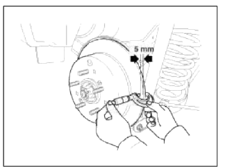
Rear Brake Disc Runout Check
1. Place a dial gauge about 5 mm (0.2 in.) from the outer circumference of the brake disc, and measure the runout of the disc.
Brake disc runout
Limit: 0.03 mm (0.00118 in.) or less (new one)
2. If the runout of the brake disc exceeds the limit specification, replace the disc, and then measure the runout again.
3. If the runout exceeds the limit specification, install the brake disc after turning it 180º and then check the runout of the brake disc again.
4. If the runout cannot be collected by changing the position of the brake disc, replace the brake disc.
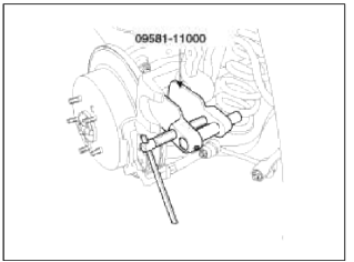
Installation
1. Installation is the reverse of removal.
2. Use a SST (09581-11000) when installing the brake caliper assembly.
READ NEXT:
 Components and ComponentsLocation | Removal - Repair procedures
Components (1)
[Hand Type] / [Foot Type]
Parking brake pedal assembly
Front parking brake cable (Foot type only)
Equalizer assembly
Rear parking brake cable
Parkin
SEE MORE:
Driver Attention Warning settings
Basic function
Driver Attention Warning will help determine
the driver's attention level by analyzing
driving pattern, driving time, etc.
while vehicle is being driven. Driver
Attention Warning will recommend a
break when the driver's attention level
falls below a certain level.
Le
Starter
Components and Components Location
Components
Front housing
Starter solenoid assembly
Lever
Lever packing
Planet shaft assembly
Planetary gear assembly
Packing
Shield
Amature assembly
Brush holder assembly
Yoke assembly
Rear housing
Through bolt
Repair procedu
Content
- Home
- Kia Sportage - Fifth generation (NQ5) - (2022-2026) - Owner's Manual
- Kia Sportage - Second generation (JEKM) (2005-2015) - Body Workshop Manual
- Kia Sportage Third generation (SL) - (2011-2016) - Service and Repair Manual
- Sitemap
- Top articles
