Kia Sportage: Engine Control Module (ECM)
Schematic Diagrams
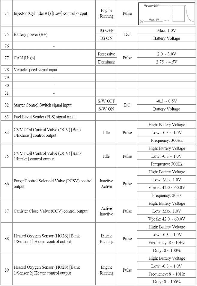
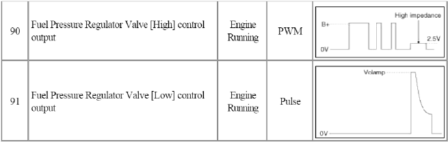
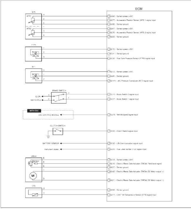
ECM Terminal And Input/Output signal
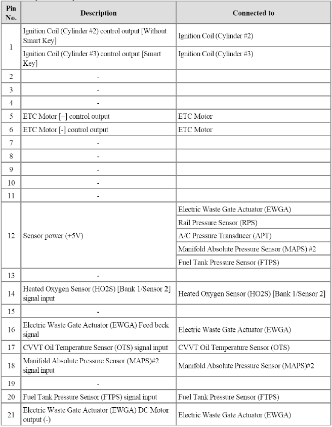
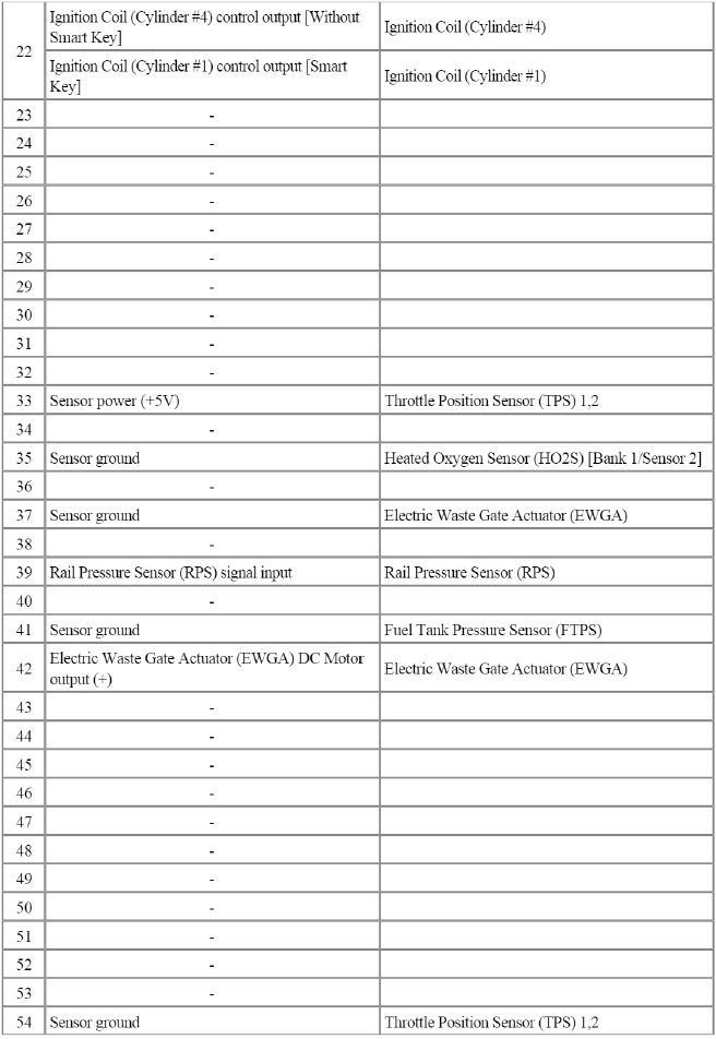
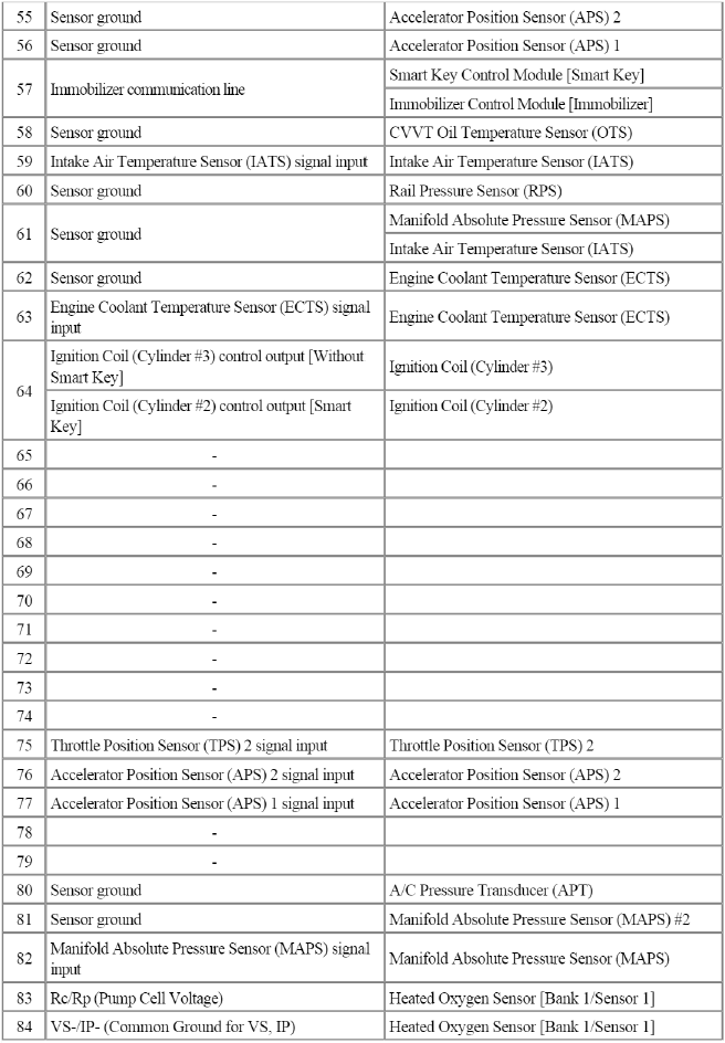
ECM Terminal Function
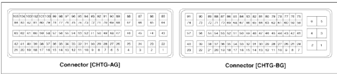
Connector [CHTG-AG]
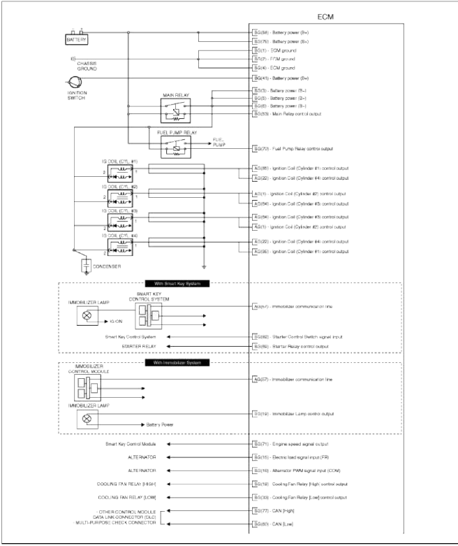
![Connector [CHTG-BG]](images/books/1921/21/index%2075.png)
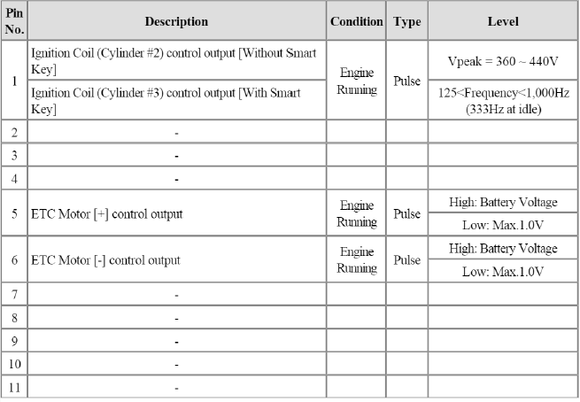
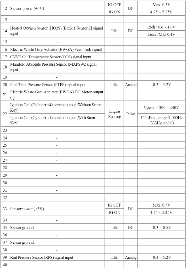
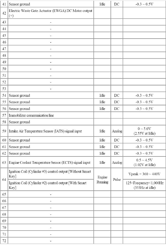
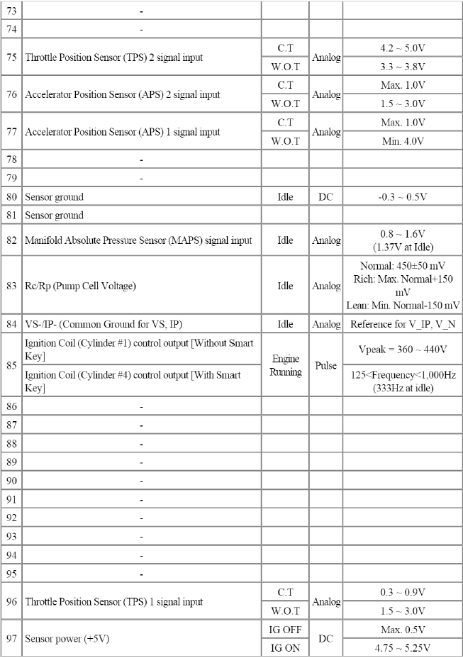
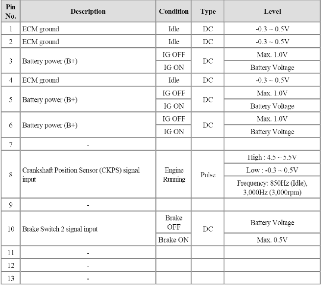
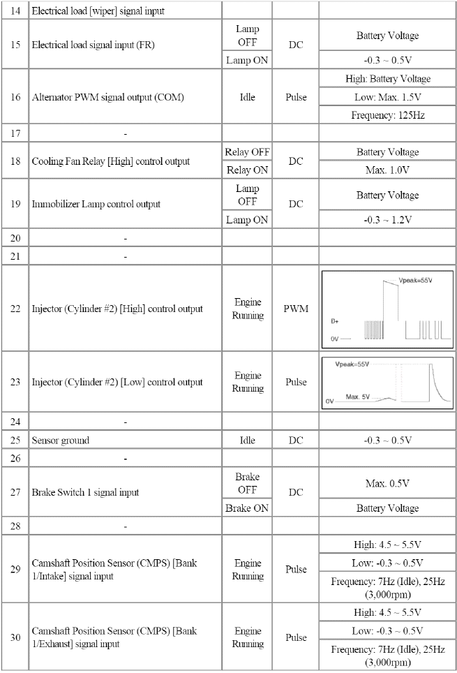
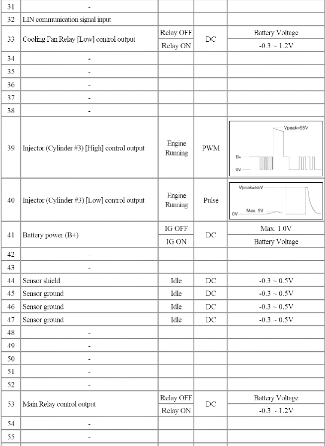
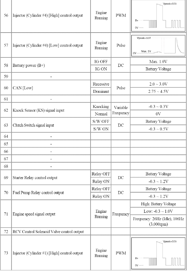
Connector [CHTG-BG]
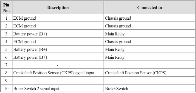
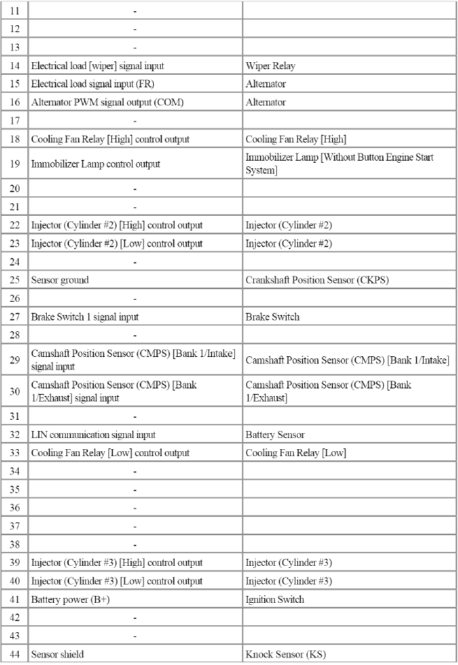
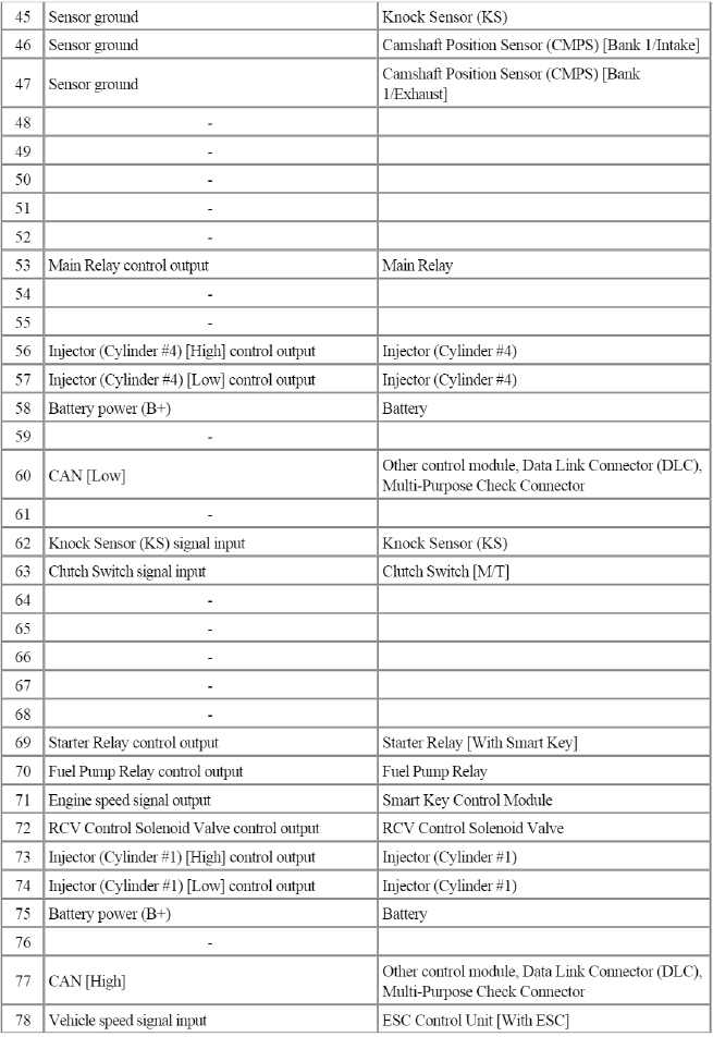
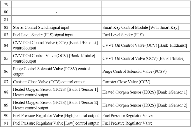
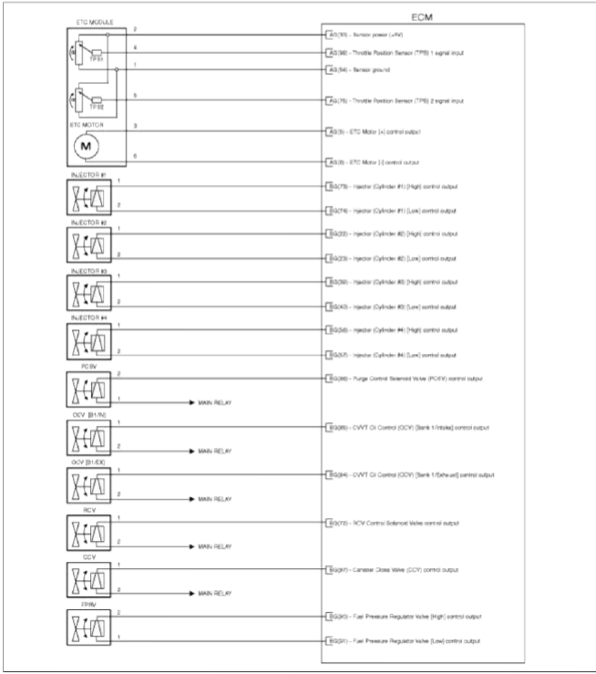
ECM Terminal Input/Output signal
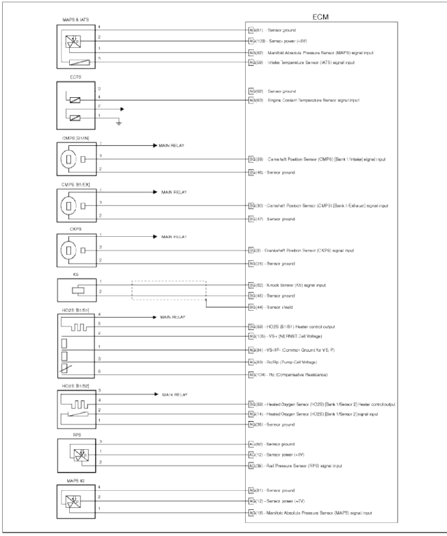
Connector [CHTG-AG]
![Connector [CHTG-BG]](images/books/1921/21/index%2084.png)
Connector [CHTG-BG]
Circuit Diagram
Repair procedures
Removal
CAUTION
When replacing the ECM, the vehicle equipped with the immobilizer must be performed procedure as below.
[In the case of installing used ECM]
- Perform "ECM Neutral mode" procedure with GDS. (Refer to "Immobilizer" in BE group)
- After finishing "ECM Neutral mode", perform "Key teaching" procedure with GDS. (Refer to "Immobilizer" in BE group)
[In the case of installing new ECM]
Perform "Key teaching" procedure with GDS. (Refer to "Immobilizer" in BE group)
CAUTION
When replacing the ECM, the vehicle equipped with the smart key system (Button start) must be performed procedure as below.
[In the case of installing used ECM]
- Perform "ECM Neutral mode" procedure with GDS. (Refer to "Smart key" in BE group)
- After finishing "ECM Neutral mode", insert the key (or press the start button) and turn it to the IGN ON and OFF position. Then the ECM learns the smart key information automatically.
[In the case of installing new ECM]
Insert the key (or press the start button) and turn it to the IGN ON and OFF position. Then the ECM learns the smart key information automatically.
1. Turn ignition switch OFF and disconnect the negative (-) battery cable.
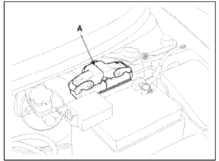
2. Disconnect the ECM Connector (A).
3. Remove the battery (Refer to "Intake And Exhaust System" in EM group).
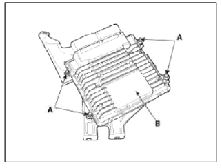
4. Remove the mounting bolts (A) and nut (B), and then remove the ECM assembly (C).
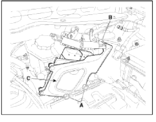
5. Remove the installation nuts (A), and then remove the ECM (B) from the bracket.
Installation
CAUTION
When replacing the ECM, the vehicle equipped with the immobilizer must be performed procedure as below.
[In the case of installing used ECM]
- Perform "ECM Neutral mode" procedure with GDS. (Refer to "Immobilizer" in BE group)
- After finishing "ECM Neutral mode", perform "Key teaching" procedure with GDS. (Refer to "Immobilizer" in BE group)
[In the case of installing new ECM]
Perform "Key teaching" procedure with GDS. (Refer to "Immobilizer" in BE group)
CAUTION
When replacing the ECM, the vehicle equipped with the smart key system (Button start) must be performed procedure as below.
[In the case of installing used ECM]
- Perform "ECM Neutral mode" procedure with GDS. (Refer to "Smart key" in BE group)
- After finishing "ECM Neutral mode", insert the key (or press the start button) and turn it to the IGN ON and OFF position. Then the ECM learns the smart key information automatically.
[In the case of installing new ECM]
Insert the key (or press the start button) and turn ft to the IGN ON and OFF position. Then the ECM learns the smart key information automatically.
1. Installation is reverse of removal.
ECM installation nut: 9.8 ~ 11.8 N.m (1.0 ~ 1.2 kgf.m,7.2 ~ 8.7 lb-ft)
ECM bracket installation bolt/nut: 9.8 ~ 11.8 N.m (1.0 ~ 1.2 kgf.m,7.2 ~ 8.7 lb-ft)
ECM Problem Inspection Procedure
1. TEST ECM GROUND CIRCUIT: Measure resistance between ECM and chassis ground using the backside of ECM harness connector as ECM side check point. If the problem is found, repair it.
Specification: Below 1Ω
2. TEST ECM CONNECTOR: Disconnect the ECM connector and visually check the ground terminals on ECM side and harness side for bent pins or poor contact pressure. If the problem is found, repair it.
3. If problem is not found in Step 1 and 2, the ECM could be faulty. If so, make sure there were no DTC's before swapping the ECM with a new one, and then check the vehicle again. If DTC's were found, examine this first before swapping ECM.
4. RE-TEST THE ORIGINAL ECM: Install the original ECM (may be broken) into a known-good vehicle and check the vehicle. If the problem occurs again, replace the original ECM with a new one. If problem does not occur, this is intermittent problem (Refer to "Intermittent Problem Inspection Procedure" in Basic Inspection Procedure).
READ NEXT:
 ETC (Electronic Throttle Control) System
Description and
Operation
Description
The Electronic Throttle Control (ETC) System consists of a throttle body with
an integrated control motor and
throttle position sensor (TPS). Instead
Manifold Absolute Pressure Sensor (MAPS)
Description
and Operation
Description
Manifold Absolute Pressure Sensor (MAPS) is a speed-density type sensor and
is installed on the surge tank. It
senses absolute pressure of the surge t
Intake Air Temperature Sensor (IATS) | Engine Coolant Temperature Sensor (ECTS)
Description and Operation
Description
Intake Air Temperature Sensor (IATS) is included inside Manifold Absolute Pressure Sensor and detects the intake air temperature.
To calculate precise a
SEE MORE:
Repair procedures
Replacement
Problems And Replacement Parts:
Replacement Of ECM And SMARTRA
In case of a defective ECM, the unit has to be replaced with a "virgin" or
"neutral" ECM. All keys have to be taught
to the new ECM. Keys, which are not taught to the ECM, are invalid for the
Description and Operation
OBD-II review
1. Overview
The California Air Resources Board (CARB) began regulation of On Board
Diagnostics (OBD) for vehicles sold in
California beginning with the 1988 model year. The first phase, OBD-L required
monitoring of the fuel metering
system, Exhaust Gas Recirculation (EGR)
Content
- Home
- Kia Sportage - Fifth generation (NQ5) - (2022-2026) - Owner's Manual
- Kia Sportage - Second generation (JEKM) (2005-2015) - Body Workshop Manual
- Kia Sportage Third generation (SL) - (2011-2016) - Service and Repair Manual
- Sitemap
- Top articles
