Kia Sportage: Components and Components Location | Rear Shock Absorber
Components Location
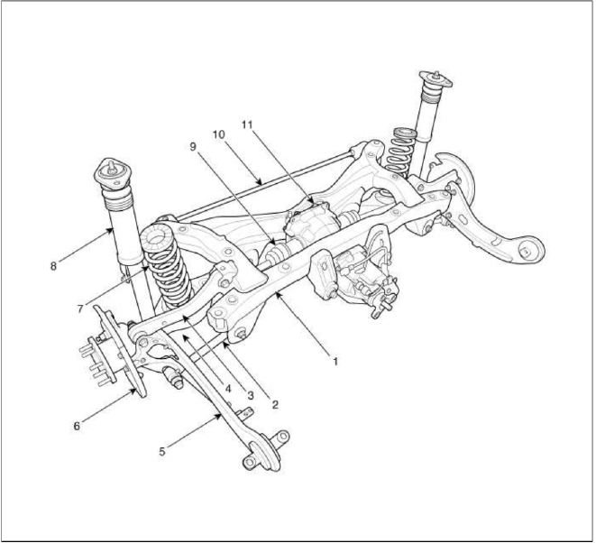
- Sub frame
- Assist arm
- Upper arm
- Lower arm
- Trailing arm
- Rear axle
- Coil spring
- Shock absorber
- Drive shaft
- Stabilizer
- Differential carrier
Components
(2WD)
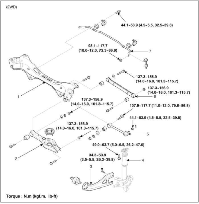
- Sub frame
- Lower arm
- Trailing arm
- Shock absorber
- Assist arm
- Upper arm
- Stabilizer bar
(4WD)
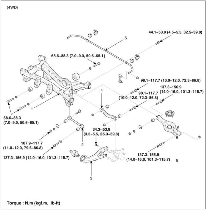
- Sub frame
- Assist arm
- Trailing arm
- Upper arm
- Lower arm
- Stabilizer bar
Rear Shock Absorber
Components and Components Location
Components
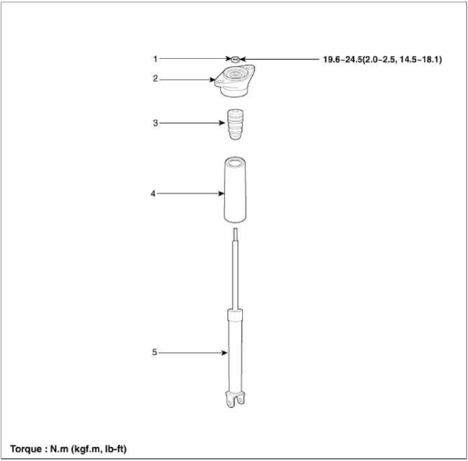
- Self locking nut
- Bracket assembly
- Bumper rubber
- Dust cover
- Shock absorber
Repair procedures
Replacement
1. Remove the rear wheel & tire.
Tightening torque: 88.3 ~ 107.9N.m (9.0 ~ 11.0kgf.m, 65.1 ~ 79.6lb-ft)
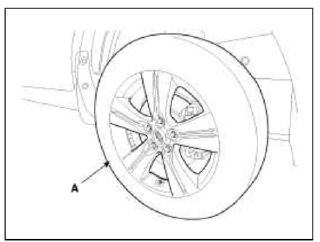
CAUTION
Be careful not to damage to the hub bolts when removing the front wheel & tire (A).
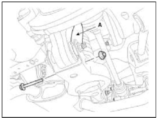
2. Loosen the bolt & nut and then disconnect the shock absorber (A) with the rear axle.
Tightening torque: 137.3 ~ 156.9N.m (14.0 ~ 16.0kgf.m, 101.3 ~ 115.7lb-ft)
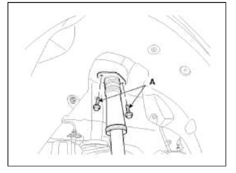
3. Loosen the shock absorber mounting bolts (A).
Tightening torque: 49.0 ~ 63.7N.m (5.0 ~ 6.5kgf.m, 36.2 ~ 47.0lb-ft)
4. Installation is the reverse of removal.
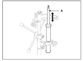
Inspection
1. Check the rubber parts for wear and deterioration.
2. Compress and extend the piston rod (A) and check that there is no abnormal resistance or unusual sound during operation.
READ NEXT:
 Rear Upper Arm | Rear Lower Arm
Repair procedures
Replacement
1. Remove the rear wheel & tire.
Tightening torque: 88.3 ~ 107.9N.m (9.0 ~ 11.0kgf.m, 65.1 ~ 79.6lb-ft)
CAUTION
Be careful not to damage to the hub bolts
SEE MORE:
Input Speed Sensor
Description and Operation
Description
Input speed sensor is a vital unit that measures the rate of rotation of the
input shaft inside the transaxle and delivers
the readings to the TCM. The sensor provides critical input data that's used in
feedback control, damper clutch
control,
Transmitter
Repair procedures
Inspection
1. Check that the red light flickers when the door lock or unlock button is
pressed on the transmitter.
2. Remove the battery (A) and check voltage if the red light doesn't flicker.
Standard voltage : 3V
3. Insert the battery (A) into the tester (09954-2pl
Content
- Home
- Kia Sportage - Fifth generation (NQ5) - (2022-2026) - Owner's Manual
- Kia Sportage - Second generation (JEKM) (2005-2015) - Body Workshop Manual
- Kia Sportage Third generation (SL) - (2011-2016) - Service and Repair Manual
- Sitemap
- Top articles
