Kia Sportage: Components and Components Location | Relay Box (Engine Compartment)
Component Location
[Engine Room Relay Box]
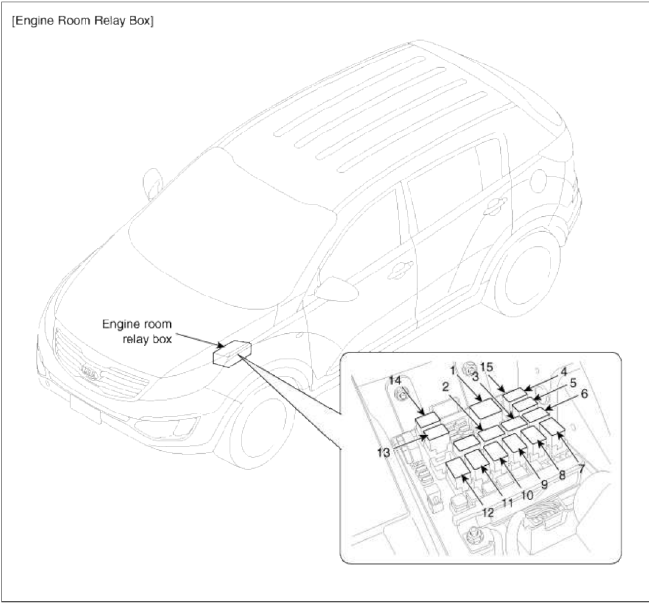
- Main relay
- Cooling fan relay (High)
- Windshield deicer relay
- Wiper relay (High)
- Wiper relay (Low)
- ATM relay
- Rear glass defogger relay
- Burglar horn relay
- Start relay
- Cooling fan relay (Low)
- Horn relay
- Blower relay
- Ð/С relay
- Fuel pump relay
- Quick braking warning system relay
[Passenger Compartment Relay]
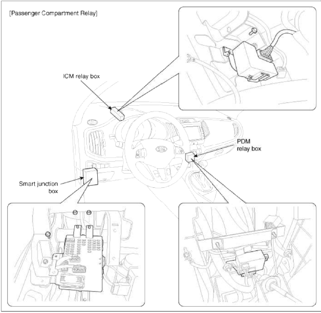
- ICM relay : Rear wiper relay, DBC (Downhill Brake Control) relay
- PDM relay : ACC relay, IG1 relay, IG2 relay
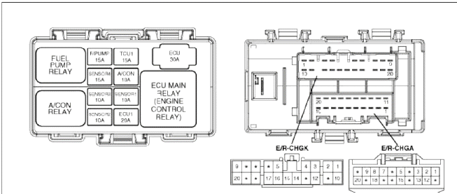
Relay Box (Engine Compartment)
Components and Components Location
Component Location
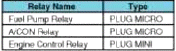
Relay Type
 USE THE DESIGNATED FUSE AND RELAY ONLY
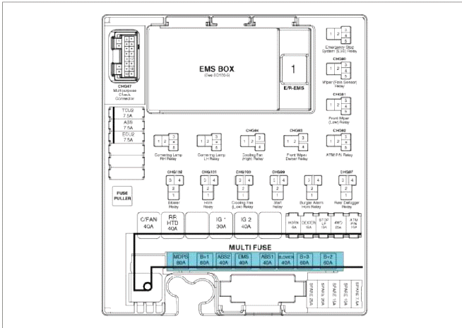
Circuit (E/R Fuse & Relay Box)
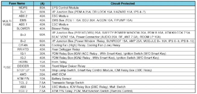
USE THE DESIGNATED FUSE AND RELAY ONLY
Relay Type
Circuit (EMS Box)
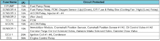
USE THE DESIGNATED FUSE AND RELAY ONLY
Repair procedures
Inspection
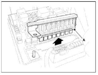
1. Disconnect the negative (-) battery terminal.
2. Pull out the relay from the engine compartment relay box
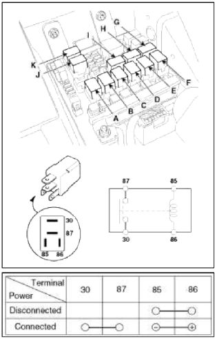
Power Relay (Type A)
Check for continuity between the terminals.
- Blower relay
- Horn relay
- Cooling fan relay (Low)
- Start relay
- Burglar horn relay
- Rear glass defogger relay
- ATM relay
- Windshield deicer relay
- Cooling fan relay (High)
- Ð/С relay
- Fuel pump relay
1. There should be continuity between the No.30 and No.87 terminals when power and ground are connected to the No.85 and No.86 terminals.
2. There should be no continuity between the No.30 and No.87 terminals when power is disconnected.
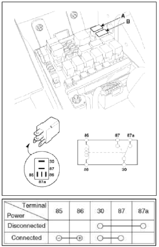
Power Relay (Type B)
Check for continuity between the terminals.
- Wiper relay (High)
- Wiper relay (Low)
1. There should be continuity between the No.30 and No.87 terminals when power and ground are connected to the No.85 and No.86 terminals.
2. There should be continuity between the No.30 and No.87 terminals when power is disconnected.
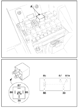
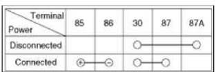
Power Relay (Type C)
Check for continuity between the terminals.
- Main relay
1. There should be continuity between the No.30 and No.87 terminals when power and ground are connected to the No.85 and No.86 terminals.
2. There should be no continuity between the No.30 and No.87 terminals when power is disconnected.
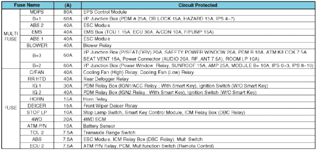
Fuse
1. Be sure there is no play in the fuse holders, and that the fuses are held securely.
2. Are the fuse capacities for each circuit correct? 3. Are there any blown fuses?
If a fuse is to be replaced, be sure to use a new fuse of the same capacity. Always determine why the fuse blew first and completely eliminate the problem before installing a new fuse.
Multi Fuse
NOTE
- Multi fuse (A) is needed to replace in the mass when it damaged only one fuse.
- When replace the multi fuse, refer to the "Engine compartment - component location" diagram exactly.
- Use the multi fuse capacities for each circuit correctly.
READ NEXT:
 Relay Box (Passenger Compartment)
Components and Components Location
Component Location
USE THE DESIGNATED FUSE AND
RELAY ONLY
Circuit (I/P Junction Box)
USE THE DESIGNATED FUSE AND
RELAY ONLY
Description and
Ope
ICM (Integrated Circuit Module) Relay Box
Components and Components Location
Component
Pin Information
Rear wiper motor
(Power)
IPM
Stop lamp
-
ESC unit
U_H_Box (ABS 7.5A
fuse)
Stop lamp switch
Stop lamp 10A fu
SEE MORE:
Power Door Mirrors
Components and Components Location
Component Location
Power door mirror
Power door mirror
switch
Power Door Mirror Switch
Schematic Diagrams
Circuit Diagram
Connector A
-
-
-
Battery
GND
ACC
-
Driver door mirror motor (vertical)
Driver door mirr
Components and Components Location | Removal - Repair procedures
Components
Intake camshaft
Exhaust camshaft
Intake CVVT assembly
Exhaust CVVT assembly
Timing chain
Timing chain guide
Timing chain tensioner arm
Timing chain tensioner
Timing chain oil jet
Balance shaft chain
Balance shaft chain tensi
Content
- Home
- Kia Sportage - Fifth generation (NQ5) - (2022-2026) - Owner's Manual
- Kia Sportage - Second generation (JEKM) (2005-2015) - Body Workshop Manual
- Kia Sportage Third generation (SL) - (2011-2016) - Service and Repair Manual
- Sitemap
- Top articles
