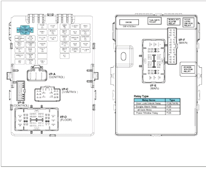
Kia Sportage: Relay Box (Passenger Compartment)
Components and Components Location
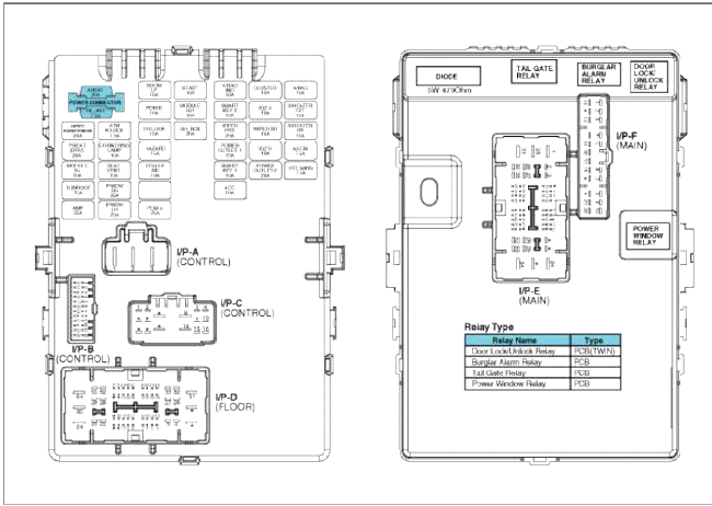
Component Location
 USE THE DESIGNATED FUSE AND
RELAY ONLY
USE THE DESIGNATED FUSE AND
RELAY ONLY
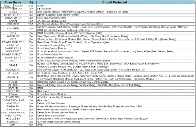
Circuit (I/P Junction Box)
USE THE DESIGNATED FUSE AND
RELAY ONLY
Description and Operation
Description
SJB (Smart Junction Box)
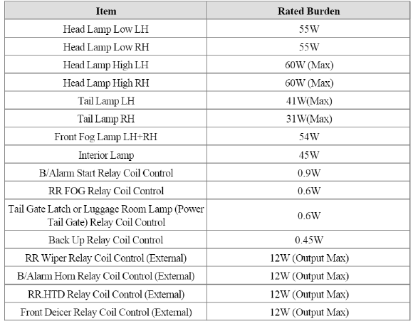
1. Specification
2. Rated Burden
3. System configuration
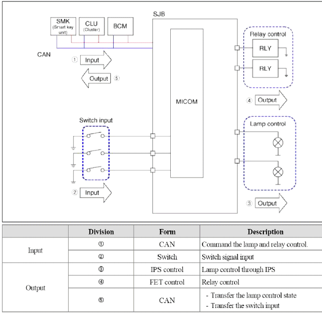
4. System block diagram
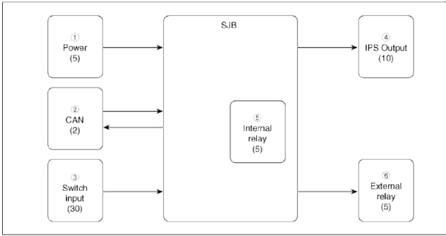
1. Power input
-
B+1
-
B+2
-
B+3
-
IGN1
-
IGN2
2. CAN
-
Tx
-
Rx
3. Switch input
-
Driver door switch
-
Assist door switch
-
Rear door switch (LH)
-
Rear door switch (RH)
-
Driver door key unlock switch
-
Assist door key unlock switch
-
Driver door key lock switch
-
Assist door key lock switch
-
Hood lock state
-
Tailgate release switch
-
Tailgate open switch
-
Power window lock switch
-
Power window unlock switch
-
Driver door unlock state
-
Assist door unlock state
-
Rear door unlock state (LH)
-
Rear door unlock state (RH)
-
Driver seat belt switch
-
Assist seat belt switch
-
Rear seat belt switch (LH)
-
Rear center seat belt switch
-
Rear seat belt switch (RH)
-
Brake fluid switch
-
Parking brake switch
-
Hand brake switch
-
Shift lever reverse gear (MT option)
-
-
-
Headlamp low switch (M/F)
-
HID option
-
Wiper parking signal
4. IPS output
-
Headlamp low (RH) - Power (B+2)
-
Headlamp high (RH) - Power (B+2)
-
External tail (RH) - Power (B+2)
-
Internal tail (LH-RH) - Power (B+2)
-
Dedicated DRL LH/RH - Power (B+2)
-
Backup lamp - Power (B+2)
-
Headlamp low (LH) - Power (B+3)
-
Headlamp high (LH) - Power (B+3)
-
Fog lamp (LH, RH) - Power (B+3)
-
External tail (LH) - Power (B+3)
5. Internal relay
-
Door lock relay
-
Door unlock relay
-
Power window relay
-
Tailgate release relay
-
Burglar alarm start relay
6. External relay
-
-
-
Rear defogger relay
-
Front deicer relay
-
Burglar horn relay
-
Rear wiper relay
5. Control function (Lamp)
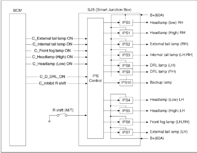
- Smart Junction Box (SJB) controls tail lamp, headlamp (low), headlamp (high) and front fog lamp output. And it diagnoses.
- It controls lamp after receiving CAN signal from BCM.
- It sends results of control state and diagnosis to BCM through CAN.
- PWM (Pulse Width Modulation) control: Rated voltage control.
If a battery voltage is over 13.2 +- 0.1 V, it controls IPS with PWM and prevents early bulb's burnt-out and II device.
It controls bulbs with controlling IPS.
A frequency is 80 +- 10 Hz (TBD) at controlling with PWM.
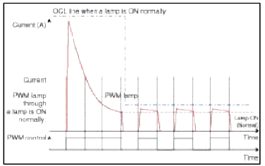
If a voltage is high, a bulb's life decreases. So, SJB keeps stable voltage to bulbs and ensures bulb's life.
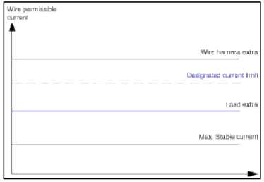
- PCL : Programmed Current Limit
If current flowed into a wire is larger than basic current which is designated to a wire, it controls IPS with PWM control or stops IPS.
- Overheat diagnosis
If high current flows into SJB within short time like as a ground short, IPS blocks an output and protects wire and load.
6. Control function - Switch input

Movement explanation
- It detects the switch state and transfers to BCM through CAN.
- It detects the switch state in the sleep state and enables to SJB wakeup function.
7. Control function - relay
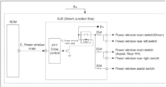
Movement explanation
- It receives the power window relay control value from BCM though CAN and controls relays.
- If C_PwdeMain (CAN signal) is ON, it makes power window relay output to
ON.
If C_PwdeMain (CAN signal) is not ON, it makes power window relay output to OFF.
8. Control function - CAN fail
SJB, in case CAN fail and IGN2 is ON, turns on head lamp (low), external tail lamp and internal tail lamp by force
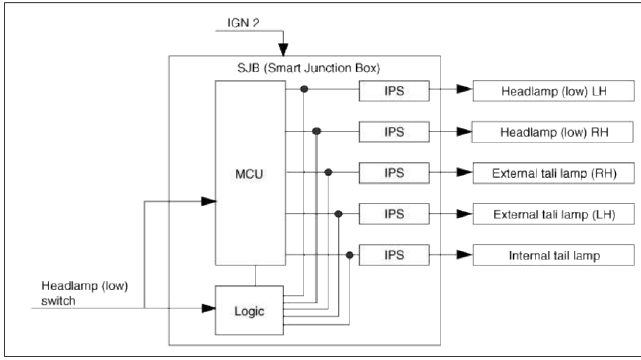
9. Hardware protection function
In case MCU is in the Dead state, SJB checks the headlamp switch state. If IGN2 is ON and headlamp (low) switch is ON, it turns on headlamp (low) by force and protects driver.
Repair procedures
Inspection
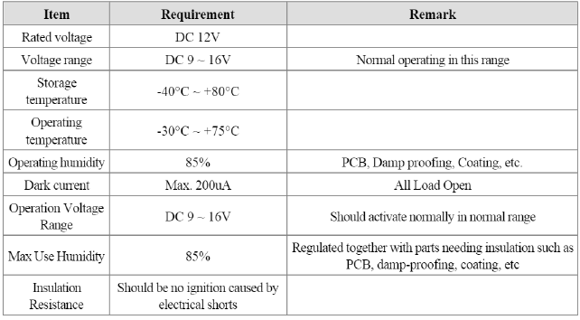
Fuse
1. Be sure there is no play in the fuse holders, and that the fuses are held securely.
2. Are the fuse capacities for each circuit correct?
3. Are there any blown fuses?
If a fuse is to be replaced, be sure to use a new fuse of the same capacity. Always determine why the fuse blew first and completely eliminate the problem before installing a new fuse.
SJB Connectors
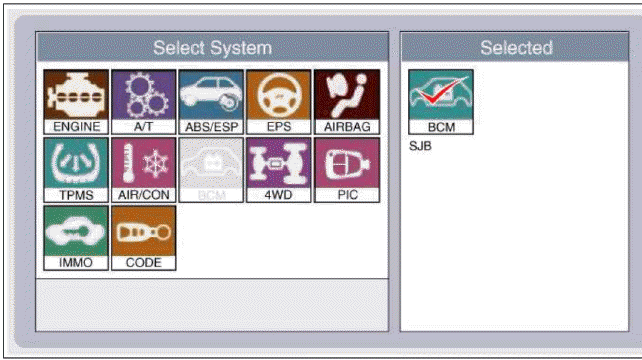
Inspection
1. The SJB can be diagnosed by using the GDS. The SJB communicates with the GDS which then displays inputs and outputs along with codes.
2. To diagnose the SJB function, select the vehicle model, BCM and SJB.
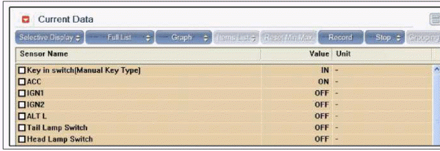
3. To consult the present input/out value of SJB. "Current DATA". It provides information of SJB input/output conditions.
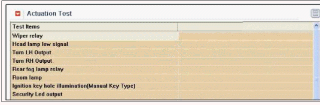
4. To perform functional test on SJB outputs, select "Actuation Test".
Removal
1. Disconnect the negative (-) battery terminal.
2. Remove the crash pad lower panel.
(Refer to the BD group - "Crash pad")
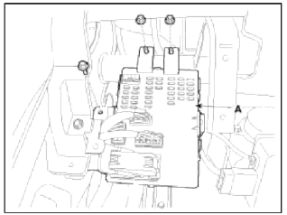
3. Remove the SJB (A) (Smart Junction Box) after removing bolt, nuts (2EA) and connectors.
Installation
1. Install SJB (Smart Junction Box).
2. Connect the SJB connectors.
3. Install the crash pad lower panel.
READ NEXT:
 ICM (Integrated Circuit Module) Relay Box
Components and Components Location
Component
Pin Information
Rear wiper motor
(Power)
IPM
Stop lamp
-
ESC unit
U_H_Box (ABS 7.5A
fuse)
Stop lamp switch
Stop lamp 10A fu
PDM Relay Box
Components and Components Location
Components
Connector A (10 pins)
Smart key unit
-
Ground
Smart key unit
-
ACC
Battery power (IGN-1)
IGN-1
-
Smart key unit
SEE MORE:
Brake fluid
Checking the brake fluid level
Check the fluid level in the reservoir
periodically. The fluid level should be
between MAX and MIN marks on the
side of the reservoir.
Before removing the reservoir cap
and adding brake fluid, clean the area
around the reservoir cap thoroughly
to prev
General Information
Specifications
Specifications
Ignition System
Starting System
Charging System
CAUTION
COLD CRANKING AMPERAGE is the amperage a battery can deliver for 30
seconds and maintain a
terminal voltage of 7.2V or greater at a specified temperature.
RESERVE CAPACITY RATING is amou
Content
- Home
- Kia Sportage - Fifth generation (NQ5) - (2022-2026) - Owner's Manual
- Kia Sportage - Second generation (JEKM) (2005-2015) - Body Workshop Manual
- Kia Sportage Third generation (SL) - (2011-2016) - Service and Repair Manual
- Sitemap
- Top articles
