Kia Sportage: ICM (Integrated Circuit Module) Relay Box
Components and Components Location
Component
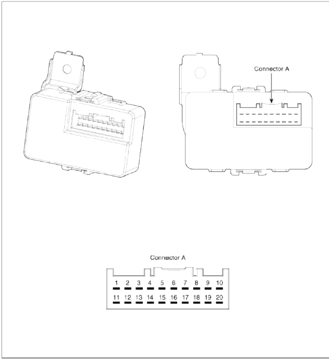
Pin Information
- Rear wiper motor (Power)
- IPM
- Stop lamp
- -
- ESC unit
- U_H_Box (ABS 7.5A fuse)
- Stop lamp switch
- Stop lamp 10A fuse
- -
- -
- IPM (Rear wiper 15 A)
- Rear wiper motor (Signal)
- -
- -
- GND
- IPM (BCM)
- IPM (Door lock 15 A)
- Door lock actuator - driver
- -
- -
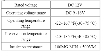
Specification
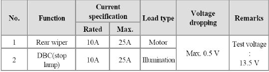
Voltage dropping specification
Schematic Diagrams
Schematic Diagram

Description and Operation
Description
The ICM relay (A) is united with rear wiper relay, and DBC relay which installed inside the lower crash pad.

Repair procedures
Inspection
Rear Wiper Relay
Check for continuity between the terminals.
1. There should be continuity between the No.11 in the A and No.12 in the A terminals when power and ground are connected to the No.2 in the A and No.11 in the A terminals.
2. There should be no continuity between the No.11 in the A and No.12 in the A terminals when power is disconnected.
DBC Relay
Check for continuity between the terminals.
1. There should be continuity between the No.3 in the A and No.8 in the A terminals when power and ground are connected to the No.5 in the A and No.6 in the A terminals.
2. There should be no continuity between the No.3 in the A and No.8 in the A terminals when power is disconnected.
Double Lock Relay
Check for continuity between the terminals.
1. There should be continuity between the No.17 in the A and No.18 in the A terminals when power and ground are connected to the No.16 in the A and No.17 in the A terminals.
2. There should be no continuity between the No.17 in the A and No.18 in the A terminals when power is disconnected.
READ NEXT:
 PDM Relay Box
Components and Components Location
Components
Connector A (10 pins)
Smart key unit
-
Ground
Smart key unit
-
ACC
Battery power (IGN-1)
IGN-1
-
Smart key unit
Components and Components Location | Instrument Cluster
Component Location
Cluster assembly
Seat belt switch
Vehicle speed sensor
Engine coolant temperature sender
Oil pressure switch
Brake fluid level warning swit
SEE MORE:
Description and Operation, Schematic Diagrams
Description and Operation
Description
The Evaporative Emission Control System prevents fuel vapor stored in fuel
tank from vaporizing into the
atmosphere. When the fuel evaporates in the fuel tank, the vapor passes through
vent hoses or tubes to a canister
filled with charcoal.
The
Limitations of Reverse Parking
Collision-Avoidance Assist
Reverse Parking Collision-Avoidance
Assist may not assist braking or warn the
driver even if there are pedestrians or
objects under the following circumstances:
Any non-factory equipment or accessory
is installed
Your vehicle is unstable due to an
accident or other causes
Bumper heigh
Content
- Home
- Kia Sportage - Fifth generation (NQ5) - (2022-2026) - Owner's Manual
- Kia Sportage - Second generation (JEKM) (2005-2015) - Body Workshop Manual
- Kia Sportage Third generation (SL) - (2011-2016) - Service and Repair Manual
- Sitemap
- Top articles
