Kia Sportage: Components and Components Location | Repair procedures
Components (1)
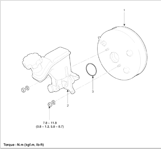
- Brake booster
- Master cylinder assembly
- O-ring
Components (2)
[2.0T - GDI ENGINE ONLY]
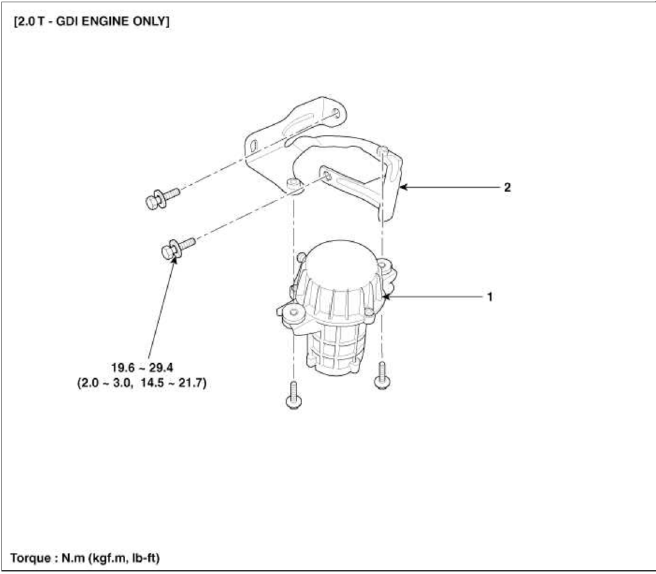
- Vacuum pump
- Bracket
Repair procedures
Brake Booster Operating Test
For simple checking of the brake booster operation, carry out the following tests.
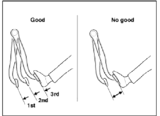
1. Run the engine for one or two minutes, and then stop it. If the pedal depresses fully the first time but gradually becomes higher when depressed succeeding times, the booster is operating properly, if the pedal height remains unchanged, the booster is inoperative.
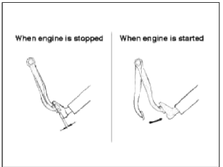
2. With the engine stopped, step on the brake pedal several times.
Then step on the brake pedal and start the engine. If the pedal moves downward slightly, the booster is in good condition. If there is no change, the booster is inoperative.
3. With the engine running, step on the brake pedal and then stop the engine. Hold the pedal depressed for 30 seconds. If the pedal height does not change, the booster is in good condition, if the pedal rises, the booster is inoperative.
If the above three tests are okay, the booster performance can be determined as good.
Even if one of the above three tests is not okay, check the check valve, vacuum hose and booster for malfunction.
Removal
Brake Booster
1. Turn ignition switch OFF and disconnect the negative (-) battery cable.
2. Disconnect the battery terminal and then remove the battery.
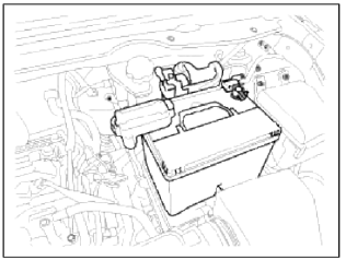
3. Disconnect the ECM connector and then ECM and battery tray.
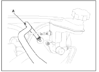
4. Disconnect the vacuum hose (A) from the brake booster.
5. Remove the master cylinder. (Refer to Master cylinder)
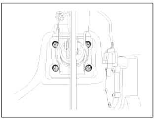
6. Remove the snap pin (A) and clevis pin (B).
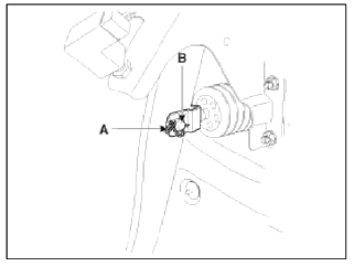
7. Remove the mounting nuts.
Tightening torque: 16.7 ~ 25.5 N.m (1.7 ~ 2.6 kgf.m, 12.3 ~ 18.8 lb-ft)
8. Remove the brake booster.
Vacuum Pump
1. Turn ignition switch OFF.
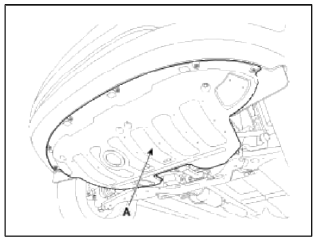
2. Remove the under covers (A).
Tightening torque: 9.8 ~ 11.8 N.m (1.0 ~ 1.2 kgf.m, 7.2 ~ 8.7 lb-ft)
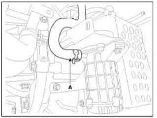
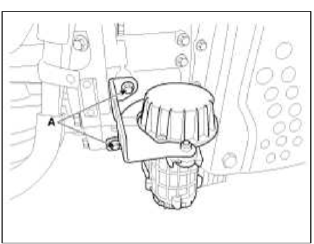
3. Disconnect the vacuum hose pump connector (A).
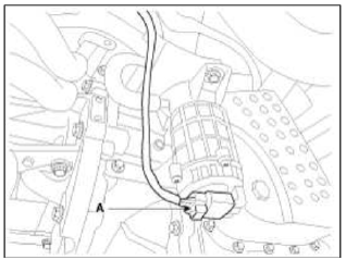
4. Disconnect the vacuum hose (A).
5. Loosen the vacuum pump bracket bolts (A), and then remove vacuum pump and bracket.
Tightening torque: 19.6 ~ 29.4 N.m (2.0 ~ 3.0 kgf.m, 14.5 ~ 21.7 lb-ft)
6. Remove the 2 bolts, and then remove the bracket from vacuum pump.
Inspection
1. Inspect the check valve in the vacuum hose, intensifier and the connecting section.
CAUTION
Do not remove the check valve from the vacuum hose.
2. Check the boot for damage.
Vacuum Pump
1. Check the brake warning lamp in the IGN ON position
NOTE
Brake warning lamp is ON as below conditions.
1. Parking brake warning.
2. Low brake fluid level warning.
3. Low brake vacuum pressure warning.
- Vacuum pump is abnormal condition
- Vacuum pump CAN communication is abnormal condition
- Vacuum switch is abnormal condition
2. Check that the brake warning lamp is ON after the release the parking brake with a sufficient brake fluid level.
If the brake warning lamp is ON, check the below points.
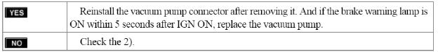
- Is the brake warning lamp ON within 5 seconds after IGN ON? (CAN Timeout Error)
NOTE
CAN Timeout Error; The brake warning lamp is ON when the communication fails more than 2 seconds between vacuum pump and cluster.
- Is the brake warning lamp ON within 45 ~ 55 seconds?

- Is the brake warning lamp ON within 15 ~ 35 seconds after removing the vacuum hose from the brake booster?

Installation
Brake Booster
1. Installation is the reverse of removal.
CAUTION
- Before installing the pin, apply the grease to the joint pin.
- Use a new snap pin whenever installing.
2. Adjust the brake pedal height and free play.
(Refer to Brake pedal height and free play adjustment)
3. After installing, bleed the brake system. (Refer to Brake system bleeding)
Vacuum Pump
1. Installation is the reverse of removal.
2. Tighten the vacuum pump mounting bolts to the specified torque.
READ NEXT:
 Master Cylinder
Components and Components Location
Components
Reservoir cap
Reservoir'
Grommet
Master
cylinder
Repair procedures
Removal
1. Turn ignition switch OFF and disconnect the n
Brake Line
Components and Components Location
Components
Repair procedures
Removal
1. Disconnect the brake fluid level switch connector, and remove the
reservoir cap.
2. Remove the brake fluid f
SEE MORE:
Folding key immobilizer system
Your immobilizer system is comprised of
a small transponder in the ignition key
and electronic devices inside the vehicle.
With the immobilizer system, whenever
you insert your ignition key into the ignition
switch and turn it to ON, it checks
and determines and verifies that the
ignition k
Spot welding
1. Commercial spot welding machines do not perform
as well as the machines used in the manufacturing
process. When spot welding, increase the number
of spot welds by 30% (1.3 times the original number
of welds).
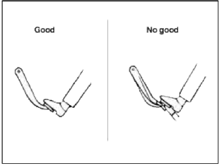
2. When spot welding, weld in the middle of the joint.
Spot welding on the
Content
- Home
- Kia Sportage - Fifth generation (NQ5) - (2022-2026) - Owner's Manual
- Kia Sportage - Second generation (JEKM) (2005-2015) - Body Workshop Manual
- Kia Sportage Third generation (SL) - (2011-2016) - Service and Repair Manual
- Sitemap
- Top articles
