Kia Sportage: Components and ComponentsLocation | Repair procedures
Component location
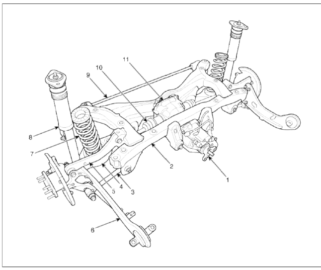
- Coupling
- Sub frame
- Assist arm
- Lower arm
- Upper arm
- Trailing arm
- Coil spring
- Shock absorber
- Stabilizer
- Drive shaft
- Differential carrier assembly
Components
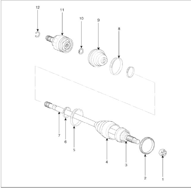
- Lock nut
- Tone wheel
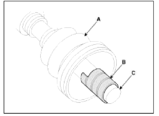
- Ð’J assembly
- Ð’J boot
- Ð’J boot big part band
- Boot small part band
- Shaft
- TJ boot big part band
- TJ boot
- Snap ring
- TJ assembly
- Circlip
Repair procedures
Replacement
1. Loosen the wheel nuts slightly.
Raise the vehicle, and make sure it is securely supported.
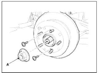
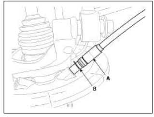
2. Remove the rear wheel and the (A) from rear hub.
Tightening torque: 88.3 ~ 107.8N.m (9.0 ~ 11.0kgf.m, 65.0 ~ 79.5lb-ft)
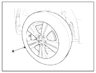
CAUTION
Be careful not to damage to the hub bolts when removing the rear wheel and tire (A).
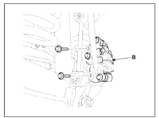
3. Remove the brake caliper mounting bolts, and then hold the brake caliper assembly (B) with wire.
Tightening torque: 78.4 ~ 98.0N.m (8.0 ~ 10.0kgf.m, 57.8 ~ 72.3lb-ft)
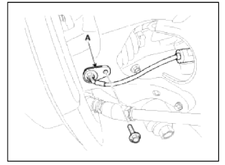
4. Remove the wheel speed sensor (A), from the knuckle.
Tightening torque: 6.8 ~ 10.8N.m (0.7 ~ 1.1kgf.m, 5.1 ~ 7.9lb-ft)
5. Remove castle nut (A) from the rear hub.
Tightening torque: 196 .1 ~ 274.5N.m (20.0 ~ 28.0kgf.m, 144.6 ~ 202.5lb-ft
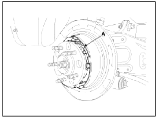
6. Remove the rear brake lining assembly (A). (Refer to BR group - Parking brake system).
7. Remove the parking brake cable (B) from the brake shoe (A).
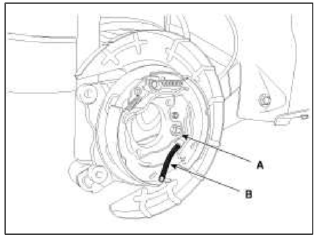
8. Remove the parking brake cable retaining (B), from the parking brake cable (A).
9. Remove the assist arm (A) from the rear axle carrier.
Tightening torque: 137.2 ~ 156.9N.m (14.0 ~ 16.0kgf.m, 101.2 ~ 115.7lb-ft)
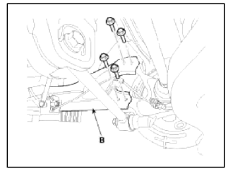
10. Remove the trailing arm (B) from the rear axle carrier.
Tightening torque: 34.3 ~ 53.9N.m (3.5 ~ 5.5kgf.m, 25.3 ~ 39.7lb-ft)
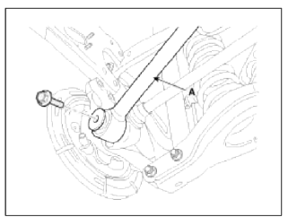
11. Remove the upper arm (A) from the rear axle carrier.
Tightening torque: 98.0 ~ 117.6N.m (10.0 ~ 12.0kgf.m, 72.3 ~ 86.7lb-ft)
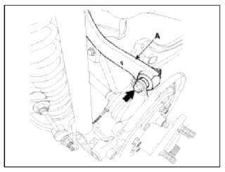
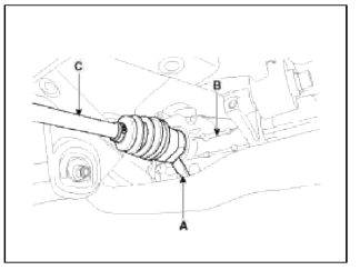
12. Push the rear axle carrier outward and separate the driveshaft (A) from the axle hub.
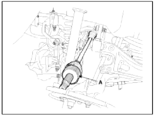
13. Insert a pry bar (A) between the differential case and joint case, and separate the driveshaft (B) from differential case.
CAUTION
- Use a pry bar (A) being careful not to damage the differential and joint.
- Do not insert the pry bar (A) too deep, as this may cause damage to the oil seal.
- Do not pull the driveshaft by excessive force it may cause components inside the joint kit to dislodge resulting in a tom boot or a damaged bearing.
- Plug the hole of the differential case with the oil seal cap to prevent contamination.
- Support the driveshaft properly.
- Replace the retainer ring whenever the driveshaft is removed from the differential case.
Inspection
1. Check the driveshaft boots for damage and deterioration.
2. Check the ball joint for wear and damage.
3. Check the splines for wear and damage.
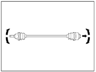
4. Check the driveshaft for cracks and wears.
5. Check the TJ outer race, inner race, cage and balls for rust or damage.
6. Check for water, foreign matter, or rust in the Ð’J boot.
CAUTION
When the BJ assembly (A) is to be reused, do not wipe away the grease.
Check that there are no foreign substances in the grease. If necessary, clean the BJ assembly (A) and replace grease.

Disassembly
CAUTION
- Do not disassemble the BJ assembly.
- Special grease must be applied to the driveshaft joint. Do not substitute with another type of grease.
- The boot band should be replaced with a new one.
1. Remove the TJ boot bands and pull the TJ boot from the TJ outer race.
- Using a pliers or flat-tipped (-) screwdriver, remove the LH boot band and LH TJ boot band from the driveshaft.
- Remove RH boot band and RH TJ boot band in the same way of LH removal procedure.
CAUTION
Be careful not to damage the boot.
2. Pull out the driveshaft from the TJ outer race.
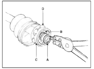
3. Remove the snap ring (A) and take out the inner race (B), cage (C) and balls (D) as an assembly.
4. Clean the inner race, cage and balls without disassembling.
5. Remove the Ð’J boot bands and pull out the TJ boot and Ð’J boot.
Reassembly
1. Wrap tape around the driveshaft splines (TJ side) to prevent damage to the boots.
2. Apply grease to the driveshaft and install the boots.
3. Apply the specified grease to the inner race (A) and cage (B). Install the cage (B) so that it is offset on the race as shown.
CAUTION
Use the grease included in the repair kit.
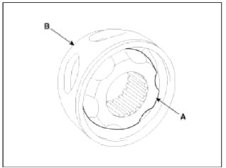
4. Apply the specified grease to the cage and fit the balls into the cage.
5. Position the chamfered side (A) as shown in the illustration. Install the inner race on the driveshaft (B), and then the snap ring.
6. Apply the specified grease to the outer race and install the Ð’J outer race onto the driveshaft
7. Apply the specified grease into the TJ boot and install the boot with a clip.
8. Tighten the TJ boot bands.
9. Add the specified grease to the Ð’ J as much as wiped away at inspection.
10. Install the boots.
11. Tighten the BJ boot bands.
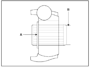
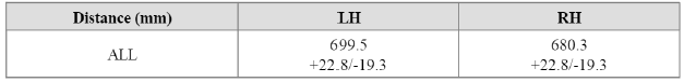
12. To control the ah in the TJ boot, keep the specified. distance between the boot bands when they are tightened.
READ NEXT:
 Propeller Shaft Assembly
Propeller Shaft
Components and Components
Location
Components
Front propeller shaft
Center bearing
bracket
Rear propeller shaft
Repair procedures
Replacement
1. After making
SEE MORE:
Relay Box (Passenger Compartment)
Components and Components Location
Component Location
USE THE DESIGNATED FUSE AND
RELAY ONLY
Circuit (I/P Junction Box)
USE THE DESIGNATED FUSE AND
RELAY ONLY
Description and
Operation
Description
SJB (Smart Junction Box)
1. Specification
2. Rated Burden
3. Syste
Underdrive Brake Control Solenoid Valve (UD/B_VFS) | Overdrive Clutch Control Solenoid Valve (OD/C_VFS)
Description and Operation
Description
Underdrive brake control solenoid valve (UD/B_VFS) is attached to the valve body. This variable force solenoid valve directly controls the hydraulic pressure inside the underdrive brake.
Specifications
Specifications
Direct control VFS [35R/C
Content
- Home
- Kia Sportage - Fifth generation (NQ5) - (2022-2026) - Owner's Manual
- Kia Sportage - Second generation (JEKM) (2005-2015) - Body Workshop Manual
- Kia Sportage Third generation (SL) - (2011-2016) - Service and Repair Manual
- Sitemap
- Top articles
