Kia Sportage: Propeller Shaft Assembly
Propeller Shaft
Components and Components Location
Components
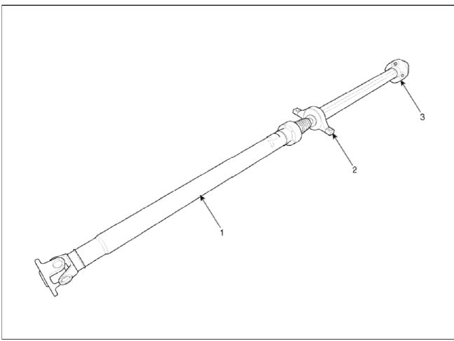
- Front propeller shaft
- Center bearing bracket
- Rear propeller shaft
Repair procedures
Replacement
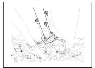
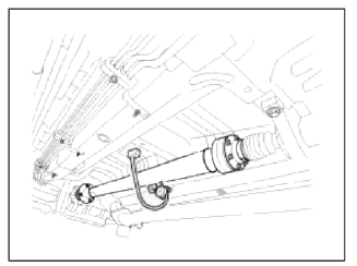
1. After making a match mark on the flange yoke and transaxle companion, remove the propeller shaft mounting bolts.
Tightening torque: 49.0 ~ 68.6N.m (5.0 ~ 7.0kgf.m, 36.1 ~ 50.6lb-ft)
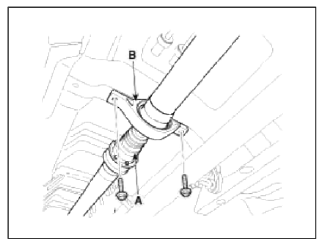
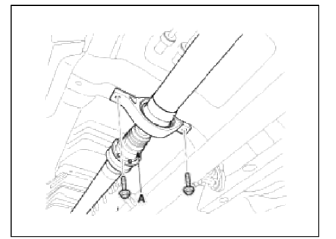
2. Remove the center bearing bracket (A) mounting bolts.
Tightening torque: 49.0 ~ 68.6N.m (5.0 ~ 7.0kgfm, 36.1 ~ 50.6lb-ft)
3. After making a match mark on the flange yoke and transaxle companion, remove the propeller shaft mounting bolts.
Tightening torque: 49.0 ~ 68.6N.m (5.0 ~ 7.0kgfm. 36.1 ~ 50.6lb-ft)
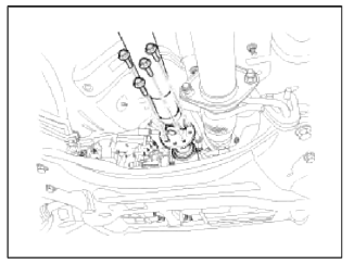
CAUTION
Use the hexagonal wrench to prevent damage of bolt head when removing bolts.
4. Install in the reverse order of removal.
Inspection
CV Joint and boots
1. Shift the transmission lever to Neutral.
2. Raise the vehicle off the ground, and support it with safety stands in the proper locations.
3. Check the center bearing for excessive play or rattle and rubber for rent. If the center bearing has excessive play or rattle and rubber has rent, replace the propeller shaft assembly.
4. Check the CV joint boot for damage and deterioration. If the boot is damaged or deteriored, replace the propeller shaft assembly.
5. Check the CV joint for excessive play or rattle. If the CV joint has excessive play or rattle, replace the propeller shaft assembly.
Propeller shaft runout
1. Install a dial indicator with its needle on the center of front propeller shaft or rear propeller shaft.
2. Turn the propeller shaft slowly and check the runout. Repeat this procedure for the other propeller shaft.
Front Propeller Shaft Runout: 0.3mm (0.012in.)
Rear Propeller Shaft Runout: 0.3mm (0.012m.)
3. If the runout on either propeller shaft exceeds the service limit, replace the propeller shaft assembly.
READ NEXT:
 Components and Components Location | Repair procedures
Component
Drive pinion nut
Oil seal
O-ring
Oil seal
Front bearing
Spacer
Rear bearing
Inner shim
Drive pinion gear
Differential carrier
SEE MORE:
Side air bag
Your vehicle is equipped with a side air
bag in each front seat.
* The actual air bags in the vehicle may
differ from the illustration.
The purpose of the air bag is to provide
the vehicle's driver and/or the front passenger
with additional protection than
that offered by the seat bel
LCD display
The LCD display modes can be changed
with the control buttons.
LCD Display Control
MODE button for changing
modes
MOVE switch for
changing
items
OK: SELECT/RESET button for setting
or resetting the selected item
LCD display modes
The LCD display provides 5 modes. You
Content
- Home
- Kia Sportage - Fifth generation (NQ5) - (2022-2026) - Owner's Manual
- Kia Sportage - Second generation (JEKM) (2005-2015) - Body Workshop Manual
- Kia Sportage Third generation (SL) - (2011-2016) - Service and Repair Manual
- Sitemap
- Top articles
