Kia Sportage: Condenser | Receiver-Drier
Components and Components Location
Component Location
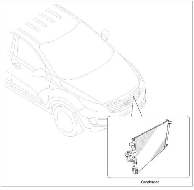
Repair procedures
Inspection
1. Check the condenser fins for clogging and damage. If clogged, clean them with water, and blow them with compressed air. If bent, gently bend them using a screwdriver or pliers.
2. Check the condenser connections for leakage, and repair or replace it, if required.
Replacement
1. Recover the refrigerant with a recovery/ recycling/ charging station.
2. Disconnect the negative (-) battery terminal.
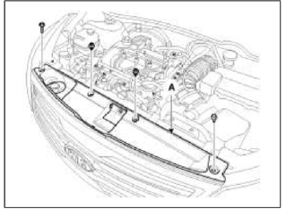
3. Remove the front bumper upper cover (A).
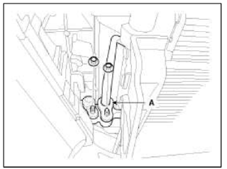
4. Remove the discharge line and liquid line (A) from the condenser.
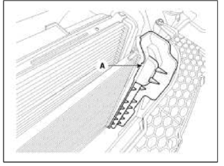
5. Remove the intercooler cover (A).
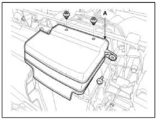
6. Remove the condenser side cover (A).
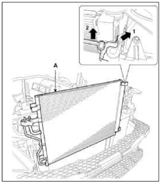
7. Remove the condenser (A) from radiator.
8. Install in the reverse order of removal, and note these items:
- If you're installing a new condenser, add refrigerant oil ND-OIL8.
- Replace the O-rings with new ones at each fitting, and apply a thin coat of refrigerant oil before installing them.
Be sure to use the right О-rings for R-134a to avoid leakage.
- Be careful not to damage the radiator and condenser fins when installing the condenser.
- Be sure to install the lower mount cushions of condenser securely into the holes.
- Charge the system, and test its performance.
Receiver-Drier
Repair procedures
Replacement
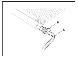
1. Remove the condenser, and then remove the bottom cap (B) with L wrench (A) from the condenser.
Tightening torque: 20~25N.m (2.0~2.5kgf.m, 14.5~18.2lb-ft)
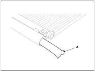
2. Remove the desiccant (A) from condenser using a long nose plier. Check for crumbled desiccant and clogged bottom cap filter.
3. Apply air conditioning compressor oil along the O-rings and threads of the new bottom cap.
4. Insert the new desiccant into the receiver drier tank. The desiccant must be sealed in vacuum before it is exposed to air for use.
5. Install the new bottom cap to the condenser.
NOTE
- Always replace the desiccant and bottom cap at the same time.
- Replace the О-rings with new ones at each fitting, and apply a thin coat of refrigerant oil before installing them. Be sure to use the right О-rings for R-134a to avoid leakage.
- Be careful not to damage the radiator and condenser tins when installing the condenser.
- Be sure to install the lower mount cushions of condenser securely into the holes.
- Charge the system, and test its performance
READ NEXT:
 Ð/С Pressure Transducer | Evaporator Temperature Sensor
Components and Components Location
Component Location
Description and Operation
Description
Ð/С pressure transducer convert the pressure value of high pressure line into volta
SEE MORE:
Cruise Control (CC)
Cruise Control (CC) (if equipped)
Cruise indicator
Set speed
Cruise Control will allow you to drive at
speeds above 20 mph (30 km/h) without
depressing the accelerator pedal.
Cruise Control operation
To set speed
Accelerate to the desired speed,
which must be more than 20 mph
Before driving
Before getting into the vehicle, you
should examine the vehicle and its surroundings.
After getting into the vehicle,
you should check a number of things
before driving.
Before entering vehicle
Be sure that all windows, outside mirror(
s), and outside lights are clean.
Check the condi
Content
- Home
- Kia Sportage - Fifth generation (NQ5) - (2022-2026) - Owner's Manual
- Kia Sportage - Second generation (JEKM) (2005-2015) - Body Workshop Manual
- Kia Sportage Third generation (SL) - (2011-2016) - Service and Repair Manual
- Sitemap
- Top articles
