Kia Sportage: Ð/С Pressure Transducer | Evaporator Temperature Sensor
Components and Components Location
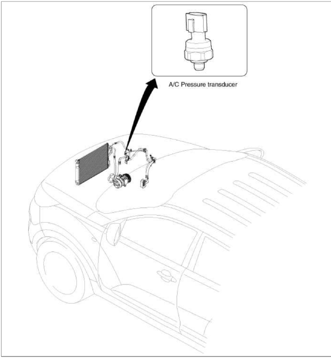
Component Location
Description and Operation
Description
Ð/С pressure transducer convert the pressure value of high pressure line into voltage value after it is measured. By voltage value, the engine ECU controls cooling fan by operating it high speed or low speed. Engine ECU stops the operation of compressor when the temperature of refrigerant line is too high or too low to optimize air conditioning system.
Repair procedures
Inspection
1. Measure the pressure of high pressure line by measuring voltage output between NO.1 and NO.2 terminals.
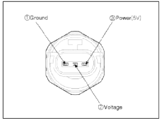
2. Inspect the voltage value whether it is sufficient to be regular value or not.
Voltage = 0.00878835 * Pressure + 0.37081095 [PSIA]
3. If the measured voltage value is not specification, replace the Ð/С pressure transducer.
Replacement
1. Disconnect the negative (-) battery terminal.
2. Recover the refrigerant with a recovery/charging station.
3. Disconnect the Ð/С pressure transducer connector (3P) (A).
Tightening torque: 10~12 N.m (1.0~1.2 kgf.m, 7.4~8.8 lb-ft)
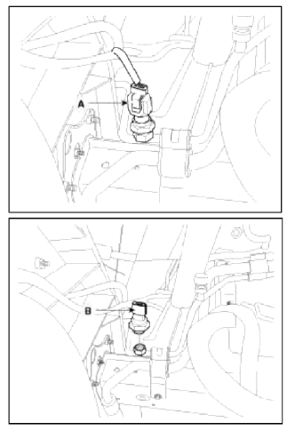
CAUTION
Take care that liquid & suction pipe are not bent.
4. Installation is the reverse order of removal.
Evaporator Temperature Sensor
Description and Operation
Description
The evaporator temperature sensor will detect the evaporator core temperature and interrupt compressor relay power in order to prevent evaporator freezing by excessive cooling.
Repair procedures
Inspection
1. Ignition "OFF".
2. Disconnect evaporator temperature sensor.
3. Using the multi-tester, Measure resistance between terminal "1" and "2" of evaporator temperature sensor.
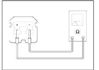
Specification
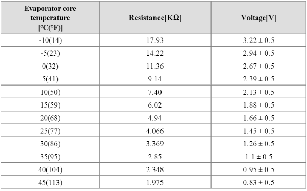

Replacement
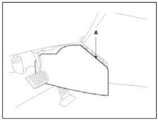
1. Remove the console extension cover (A).
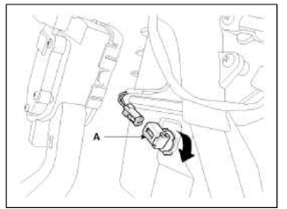
2. Remove the evaporator temperature sensor (A), by pulling it after rotating 90º in a clockwise direction.
3. Installation is the reverse order of removal.
READ NEXT:
 Photo Sensor | Ambient Sensor
Description and Operation
Description
1. The photo sensor is located at the right of defrost nozzle.
2. The photo sensor contains a photovoltaic (sensitive to sunlight) diode. The solar radiation
SEE MORE:
Yaw-rate and Lateral G Sensor | ESC OFF Switch
Description and Operation
Description
When the vehicle is turning with respect to a vertical axis the yaw rate sensor detects the yaw rate electronically by the vibration change of plate fork inside the yaw rate sensor.
If yaw velocity reaches the specific velocity after it detects the veh
Rear Door
Components and Components Location
Components
Rear door trim
Rear door inside handle cap
Rear door belt inside weatherstrip
Rear door trim seal
Rear door module
Rear door panel
Rear door belt weatherstrip
Rear door frame garnish
Rear door body side weatherstrip
Rear do
Content
- Home
- Kia Sportage - Fifth generation (NQ5) - (2022-2026) - Owner's Manual
- Kia Sportage - Second generation (JEKM) (2005-2015) - Body Workshop Manual
- Kia Sportage Third generation (SL) - (2011-2016) - Service and Repair Manual
- Sitemap
- Top articles
