Kia Sportage: Description and Operation, Flow Diagram | Schematic Diagrams | Components and Components Location, Repair procedures
Description and Operation
Description
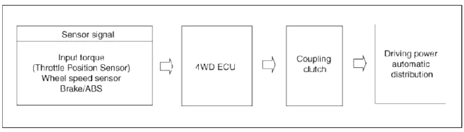
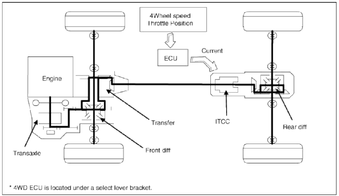
4WD ECU processes signals from various sensors and determines the current road and driving conditions. The ECU then utilizes this information to implement precision control over the 4WD coupling's multi-plate clutch and variably adjust the amount of torque delivered to the rear wheels.
Flow Diagram
Power Flow Diagram
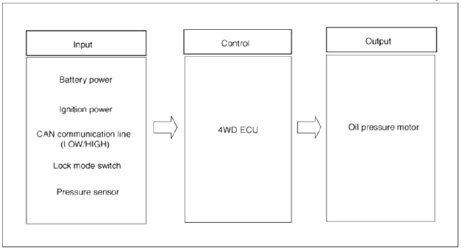
4WD ECU Input&Output Diagram
Schematic Diagrams
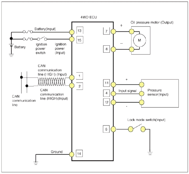
Circuit Diagram
4WD ECU Connector
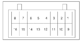
- Oil pressure motor A
- Oil pressure motor Ð’
- Lock mode switch
- -
- Input sensor signal (+)
- -
- CAN communication line (High)
- CAN communication line (Low)
- -
- -
- -
- IG power
- Ground
- Battery power
- Input sensor signal(-)
- Pressure sensor (Input)
- -
- -
4WD ECU Circuit Diagram
Components and Components Location, Repair procedures
Components and Components Location
Component Location
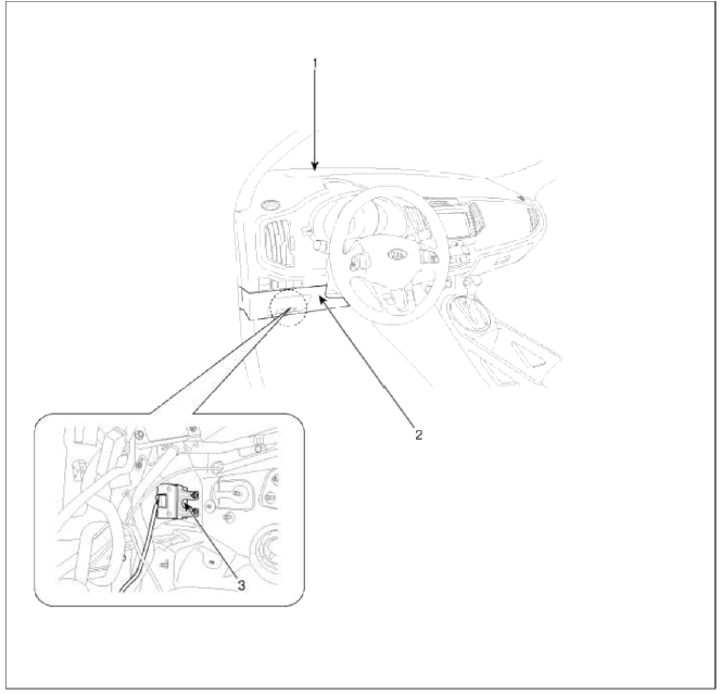
- Crash pad
- Crash lower panel
- 4WD ECU
Repair procedures
Replacement
CAUTION
Prior to replacing the 4WD ECU, check the 4WD ECU's clutch learing with the GDS tool. (Refer to "Coupling assembly" in 4WD group)
1. Remove the lower panel. (Refer to "Crash Pad" in BD group)
2. Remove the IPM. (Refer to "Fuses and Relays" in BE group)
3. Remove the parking brake pedal. (Refer to "Parking Brake System" in BR group
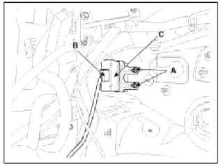
4. Remove the 4WD ECU (C) after removing the nut (A-2ea) and the connector (B).
Tightening torque: 9.8 ~ 11.8 N.m (1.0 ~ 1.2 kgf.m, 7.2 ~ 8.7 lb-ft)
5. Installation is the reverse of removal.
CAUTION
Prior to installing a new ECU, upload the original ECU's clutch learing to the replacement ECU using the GDS tool. (Refer to "Coupling assembly" in 4WD group)
READ NEXT:
SEE MORE:
 Components and Components Location | Windshield Wiper-Washer Switch
Component Location
Windshield wiper arm & blade
Wiper & washer switch
Windshield washer hose
Windshield wiper motor & linkage
Washer motor (Front)
Washer reservoir
Washer motor (Rear)
Rear washer hose & nozzle
Front wiper relay (
Components and Components Location | Power Door Lock Actuators
Component Location
Driver power window switch
Assist power window switch
SJB (Smart Junction Box)
Door lock switch
Tailgate lock actuator & switch
Front door lock actuator & switch
Rear door lock actuator & switch
Power Door Lock Actuator
Content
- Home
- Kia Sportage - Fifth generation (NQ5) - (2022-2026) - Owner's Manual
- Kia Sportage - Second generation (JEKM) (2005-2015) - Body Workshop Manual
- Kia Sportage Third generation (SL) - (2011-2016) - Service and Repair Manual
- Sitemap
- Top articles
