Kia Sportage: ETC (Electronic Throttle Control) System
Description and Operation
Description
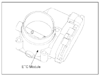
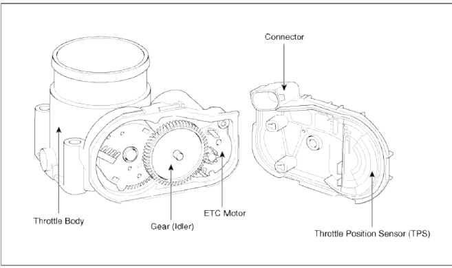
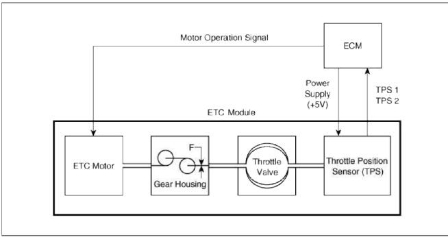
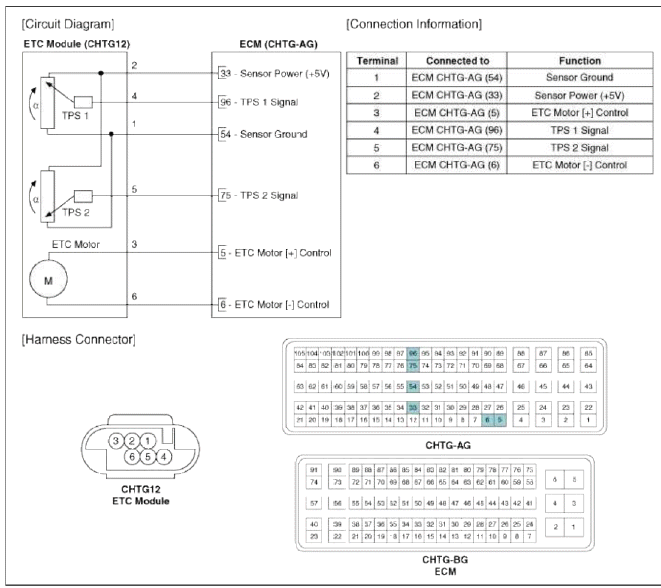
The Electronic Throttle Control (ETC) System consists of a throttle body with an integrated control motor and throttle position sensor (TPS). Instead of the traditional throttle cable, an Accelerator Position Sensor GAPS) is used to receive driver input. The ECM uses the APS signal to calculate the target throttle angle; the position of the throttle is then adjusted via ECM control of the ETC motor. The TPS signal is used to provide feedback regarding throttle position to the ECM. Using ETC, precise control over throttle position is possible; the need for external cruise control modules/cables is eliminated.
Schematic Diagram
Troubleshooting
Fail-Safe Mode
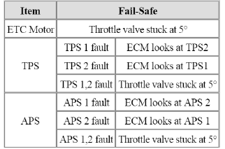
NOTE
When throttle value is stuck at 5º, engine speed is limited at below 1,500 rpm and vehicle speed at maximum 40 ~ 50 km/h (25 ~ 31 mph)
Specifications
Specification
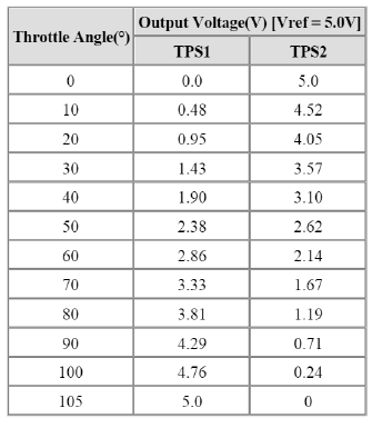
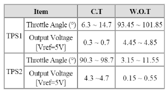
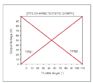
[Throttle Position Sensor (TPS) ]
![[ETC Motor]](images/books/1921/21/index%20114.png)
[ETC Motor]
Schematic Diagrams
Circuit Diagram
Repair procedures
Inspection
Throttle Position Sensor (TPS)
1. Connect the GDS on the Data Link Connector (DLC).
2. Stall the engine and measure the output voltage of TPS 1 and 2 at C.T. and W.O.T
Specification: Refer to "Specification"
3. Turn the ignition switch OFF and disconnect the scan tool from the DLC.
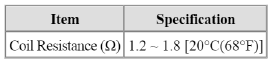
4. Disconnect the ETC module connector and measure the resistance between the ETC module terminals 1 and 2.
Specification: Refer to "Sensor Resistance"
ETC Motor
1. Turn the ignition switch OFF.
2. Disconnect the ETC module connector.
3. Measure resistance between the ETC module terminals 3 and 6.
4. Check that the resistance is within the specification
Specification: Refer to "Specification"
Removal
1. Turn the ignition switch OFF and disconnect the battery negative (-) cable.
2. Remove the resonator and the air intake hose (Refer to "Intake And Exhaust System" in EM group).
3. Disconnect the ETC module connector.
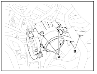
4. Disconnect the coolant hoses (B).
5. Remove the installation bolts (A), and then remove the ETC module from the engine.
Installation
CAUTION
- Install the component with the specified torques.
- Note that internal damage may occur when the component is dropped. If the component has been dropped, inspect before installing.
1. Installation is reverse of removal.
Electronic throttle body Installation bolt: 9.8 ~ 11.8 N.m (1.0 ~ 1.2 kgf.m, 7.2 ~ 8.7 lb-ft)
READ NEXT:
 Manifold Absolute Pressure Sensor (MAPS)
Description
and Operation
Description
Manifold Absolute Pressure Sensor (MAPS) is a speed-density type sensor and
is installed on the surge tank. It
senses absolute pressure of the surge t
Intake Air Temperature Sensor (IATS) | Engine Coolant Temperature Sensor (ECTS)
Description and Operation
Description
Intake Air Temperature Sensor (IATS) is included inside Manifold Absolute Pressure Sensor and detects the intake air temperature.
To calculate precise a
SEE MORE:
Accumulated driving information mode
This display shows the accumulated trip
distance, the average fuel efficiency, and
the total driving time.
Accumulated info
Accumulated trip distance
Average fuel efficiency
Total driving time
Accumulated information is calculated
after the vehicle has run for more
than
Safe Exit Warning operation
Warning
Safe Exit Warning warns the following
actions.
Collision warning when exiting vehicle
Watch for traffic
The warning light on the side view
mirror will blink and the warning message
will appear on the cluster, and an
audible warning will sound.
Safe Exit Warning w
Content
- Home
- Kia Sportage - Fifth generation (NQ5) - (2022-2026) - Owner's Manual
- Kia Sportage - Second generation (JEKM) (2005-2015) - Body Workshop Manual
- Kia Sportage Third generation (SL) - (2011-2016) - Service and Repair Manual
- Sitemap
- Top articles
