Kia Sportage: Front Bumper | Rear Bumper
Components and Components Location
Components
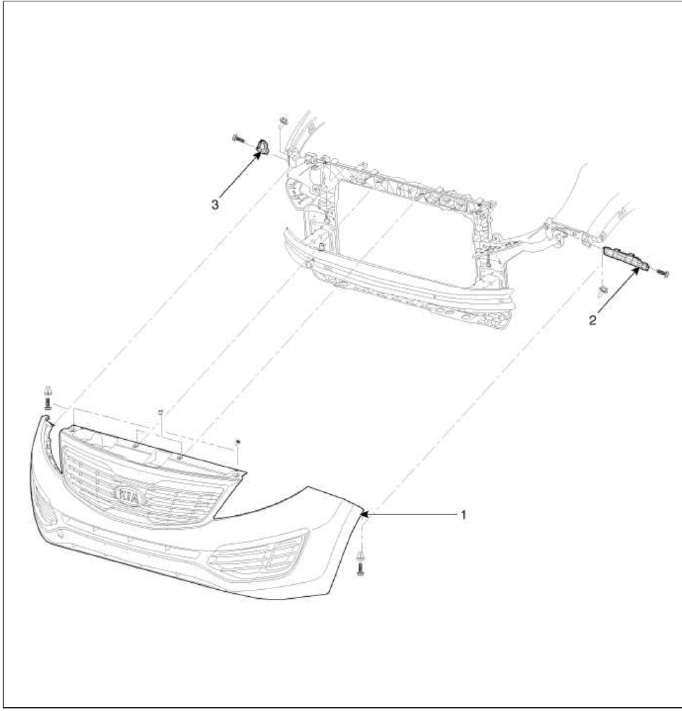
- Front bumper cover
- Front bumper side bracket [LH]
- Front bumper side bracket [RH]
Repair procedures
Replacement
CAUTION
- Put on gloves to protect your hands.
- Use a plastic panel removal tool to remove interior trip pieces to without marring the surface.
- Take care not bend or scratch the cover and other parts.
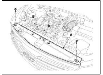
1. Loosen the radiator upper cover (A) mounting clips and bolts.
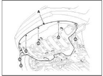
2. Remove the under cover (A) mounting clips.
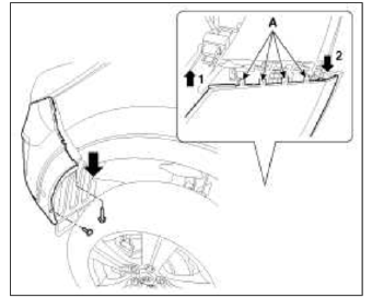
3. After loosening the front bumper side's mounting screw, then disconnect the side's.
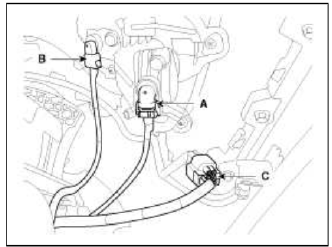
4. Disconnect the fog lamp (A), turn signal lamp (B), front sensor (C).
5. Remove the front bumper.
[LH]
![[RH]](images/books/1921/6/index%205.png)
[RH]
6. Installation is the reverse of removal.
NOTE
- Make sure the connector is plugged in properly.
- Replace any damage clips.
Rear Bumper
Components and Components Location
Components
- Front bumper cover
- Front bumper side bracket [RH]
- Front bumper side bracket [LH]
Repair procedures
Replacement
CAUTION
- Put on gloves to protect your hands.
- Use a plastic panel removal tool to remove interior trip pieces to without marring the surface.
- Take care not bend or scratch the cover and other parts.
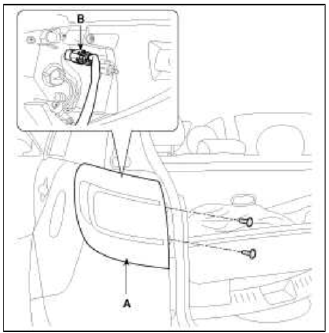
1. After loosening the mounting screws, then remove the rear combination lamp (A).
2. Push the lock pin, disconnect the connector (B).
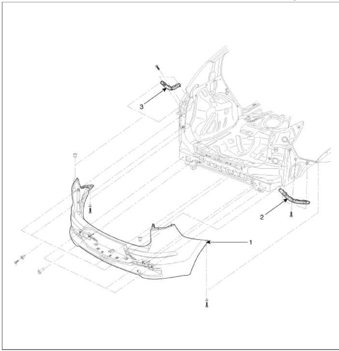
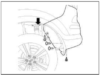
3. After loosening the rear bumper side's mounting screws and clip, then disconnect the side's.
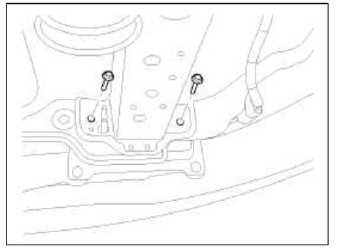
4. Loosen the mounting bolts.
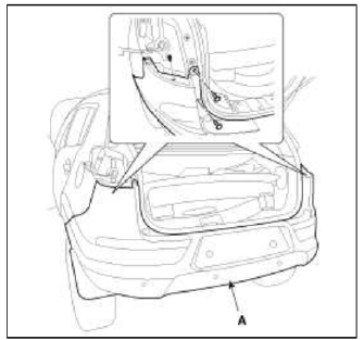
5. After loosening the mounting screws and clip, then remove the rear bumper (A).
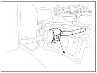
6. Push the lock pin, disconnect the rear bumper main connector (A).
7. Installation is the reverse of removal.
NOTE
- Make sure the connector is plugged in properly.
- Replace any damage clips.
READ NEXT:
 Front Seat
Components and Components
Location
Components
Headrest
Headrest guide
Front seat back cover
Front seat back heater
Front seat back pad
Front seat back power lumbar
Front seat
SEE MORE:
Feature of Seat Leather
Front seat
Sliding: Forward and Backward
Reclining: Back angle
Seat cushion height
Seat cushion tilt
Lumbar support*
Driver position memory system*
Headrest
Rear seat
Seat back folding
Armrest
Headrest
Seatback folding*
* : if equipped
WARNING
Loose objects
Loo
Vehicle protection
1. Cover the seats before performing any procedure to
keep them from getting dirty.
2. Cover all glasses, seats and mats with a heat
resistant cover when welding.
3. Protect moldings, garnishes and ornaments.
A word about safety
1. Wear the appropriate safety equipment that is
necessary f
Content
- Home
- Kia Sportage - Fifth generation (NQ5) - (2022-2026) - Owner's Manual
- Kia Sportage - Second generation (JEKM) (2005-2015) - Body Workshop Manual
- Kia Sportage Third generation (SL) - (2011-2016) - Service and Repair Manual
- Sitemap
- Top articles
