Kia Sportage: Front Cross Member
Repair procedures
Replacement
1. Remove the front wheel & tire.
Tightening torque: 88.3 ~ 107.9N.m (9.0 ~ 11.0kgf.m, 65.1 ~ 79.6lb-ft)
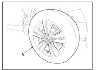
CAUTION
Be careful not to damage to the hub bolts when removing the front wheel & tire (A).
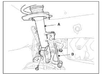
2. Disconnect the stabilizer link (B) from the front strut assembly (A) after loosening the nut.
Tightening torque: 98.1 ~ 117.7N.m (10.0 ~ 12.0kgf.m, 72.3 ~ 86.8lb-ft)
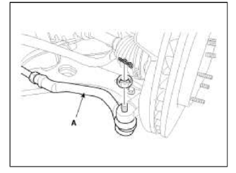
3. Remove the split pin and castle nut and then disconnect the tie-rod end (A) from the front knuckle.
Tightening torque: 34.3 ~ 44.1N.m (3.5 ~ 4.5kgf.m, 25.3 ~ 32.5lb-ft)
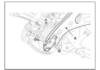
4. Loosen the bolt & nut and then remove the lower arm (A).
Tightening torque: 98.1 ~ 117.7N.m (10.0 ~ 12.0kgf.m, 72.3 ~ 86.8lb-ft)
5. Remove the dust cover.
6. Loosen the bolt (A) and then disconnect the universal joint assembly from the pinion of the steering gear box.
Tightening torque: 29.4 ~ 34.3N.m (3.0 ~ 3.5kgf.m, 21.7 ~ 25.3lb-ft)
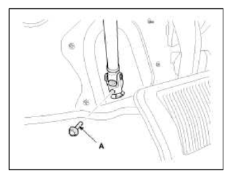
CAUTION
- Keep the neutral-range to prevent the damage of the clock spring inner cable when you handle the steering wheel.
- Do not use the bolt again.
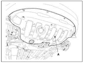
7. Remove the under cover (A).
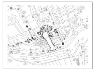
8. Loosen the bolt (A) & nut (B) and then remove the roll rod stopper.
Tightening torque: 107 .9 ~ 127.5N.m (11.0 ~ 13.0kgf.m, 79.6 ~ 94.0lb-ft)
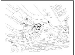
9. Disconnect the muffler rubber hanger (A).
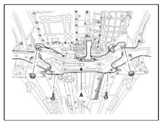
10. Loosen the bolts & nuts and then remove the sub frame.
Tightening torque: 176. 5 ~ 196.1N.m (18.0 ~ 20.0kgf.m, 130.2 ~ 144.7lb-ft)
11. Remove the front lower arm.
(Refer to Front lower arm)
12. Remove the front stabilizer.
(Refer to Front stabilizer)
13. Remove the steering gearbox.
(Refer to "Steering Gearbox" in ST group)
14. Installation is the reverse of removal.
READ NEXT:
 Components and Components Location | Rear Shock Absorber
Components Location
Sub frame
Assist arm
Upper arm
Lower arm
Trailing arm
Rear axle
Coil spring
Shock absorber
Drive shaft
Stabilizer
SEE MORE:
Exterior Lighting Control
Tail Lamp Control
1. This function describes the following features
Turn on and off Tail Lamp by switch input.
Turn on and off Tail Lamp in Auto Light Control command.
Automatically cut off Tail Lamps if a driver forgets to turn them off.
Output control of Tail Lamp.
2. Tail Auto
Reassembly - Repair procedures
NOTE
Thoroughly clean all parts to assembled.
Before installing the parts, apply fresh engine oil to all sliding
and rotating surfaces.
Replace all gaskets, O-rings and oil seals with new parts.
1. Assemble the piston and connecting rod.
The piston front mark and the connecting rod
Content
- Home
- Kia Sportage - Fifth generation (NQ5) - (2022-2026) - Owner's Manual
- Kia Sportage - Second generation (JEKM) (2005-2015) - Body Workshop Manual
- Kia Sportage Third generation (SL) - (2011-2016) - Service and Repair Manual
- Sitemap
- Top articles
