Kia Sportage: Fuel Tank
Repair procedures
Removal
1. Release the residual pressure in fuel line (Refer to "Release Residual Pressure in Fuel Line" in this group).
2. Remove the rear seat cushion (Refer to "Seat" in BD group).
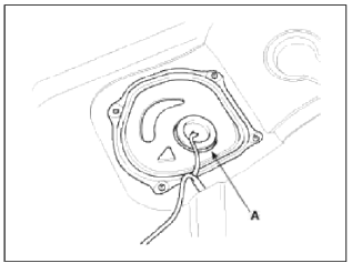
3. Remove the fuel pump service cover (A).
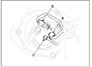
4. Disconnect the fuel рumр connector (A) and the fuel tank pressure sensor connector (B).
5. Disconnect the fuel feed tube quick connector (C).
6. Remove the rear - LH wheel & tire.
7. Lift the vehicle and support the fuel tank with a jack.
8. Remove the center muffler assembly (Refer to "Intake And Exhaust System" in EM group).
9. Remove the propeller shaft (Refer to "Propeller Shaft Assembly" in DS group) [4WD].
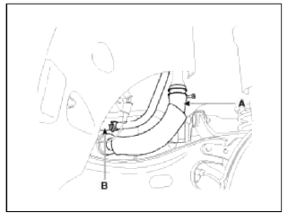
10. Disconnect the fuel filler hose (A) and the ventilation hose (B).
11. Disconnect the canister close valve connector (A).
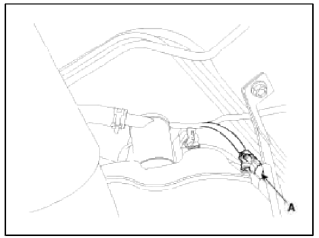
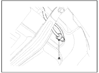
12. Disconnect the vapor tube quick-connector (A).
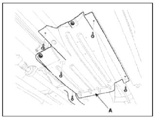
13. Remove the wider cover (A).
14. Remove the fuel tank from the vehicle after removing the fuel tank band (A).
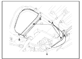
NOTE
When removing the fuel tank, the fuel tank must be tilted because of interfering with coupling.
Installation
1. Installation is reverse of removal.
Fuel tank band installation nut: 39.2 ~ 54.0 N.m (4.0 ~ 5.5 kgf.m, 28.9 ~ 39.8 lb-ft)
READ NEXT:
 Fuel Pump
Repair procedures
Inspection
[Fuel pump]
1. Turn the ignition switch OFF, and then remove battery (-) cable.
2. Remove the fuel pump assembly.
3. Check motor operation by fuel pump conn
Filler-Neck Assembly | Accelerator Pedal | Delivery Pipe
Repair procedures
Removal
1. Remove the rear-LH wheel, tire, and the inner wheel house.
2. Disconnect the fuel filler hose (A) and the ventilation hose (B).
3. Open the fuel filler door and unfa
SEE MORE:
Input Speed Sensor
Description and Operation
Description
Input speed sensor is a vital unit that measures the rate of rotation of the
input shaft inside the transaxle and delivers
the readings to the TCM. The sensor provides critical input data that's used in
feedback control, damper clutch
control,
Components and Components Location | Rear Shock Absorber
Components Location
Sub frame
Assist arm
Upper arm
Lower arm
Trailing arm
Rear axle
Coil spring
Shock absorber
Drive shaft
Stabilizer
Differential carrier
Components
(2WD)
Sub frame
Lower arm
Trailing arm
Content
- Home
- Kia Sportage - Fifth generation (NQ5) - (2022-2026) - Owner's Manual
- Kia Sportage - Second generation (JEKM) (2005-2015) - Body Workshop Manual
- Kia Sportage Third generation (SL) - (2011-2016) - Service and Repair Manual
- Sitemap
- Top articles
