Kia Sportage: Coolant
Repair procedures
Refilling And Bleeding
WARNING
Never remove the radiator cap when the engine is hot. Serious scalding could be caused by hot fluid under high pressure escaping from the radiator.
CAUTION
When pouring engine coolant, be sure to shut the relay box lid and not to let coolant spill on the electrical parts or the paint. If any coolant spills, rinse it off immediately.
1. Make sure the engine and radiator are cool to the touch.
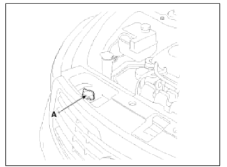
2. Remove radiator cap (A).

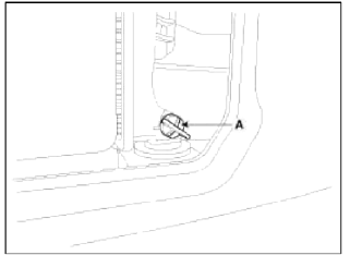
3. Loosen the plug (A), and drain the coolant.

4. Tighten the radiator drain plug securely.
5. After draining engine coolant in the reservoir tank, clean the tank.
6. Fill the radiator with water through the radiator cap and tighten the cap.
NOTE
To most effectively bleed the air, pour the water slowly and press on the upper/lower radiator hoses.
7. Start the engine and allow to come to normal operating temperature. Wait for the cooling fans to turn on several times. Accelerate the engine to aid in purging trapped air. Shut engine off.
8. Wait until the engine is cool.
9. Repeat steps 1 to 8 until the drained water runs clear.
10. Fill fluid mixture with coolant and water (55-60%) (except for North America, Europe and China: 45-50%) slowly through the radiator cap. Push the upper/lower hoses of the radiator so as bleed air easily.
NOTE
- Use only genuine antifreeze/coolant.
- For best corrosion protection, the coolant concentration must be
maintained year-round at 55%
(except for North America, Europe and China : 45%) minimum.
Coolant concentrations less than 55% (except for North America, Europe and China : 45%) may not provide sufficient protection against corrosion or freezing.
- Coolant concentrations greater then 60% will impair cooling efficiency and are not recommended.
CAUTION
- Do not mix different brands of antifreeze/coolants.
- Do not use additional rust inhibitors or antirust products; they may not be compatible with the coolant.
11. Start the engine and run until coolant circulates.
When the cooling fan operates and coolant circulates, refill coolant through the radiator cap.
12. Repeat 11 until the cooling fan 3 ~ 5 times and bleed air sufficiently out of the cooling system.
13. Install the radiator cap and fill the reservoir tank to the "MAX" (or "F") line with coolant.
14. Run the vehicle under idle until the cooling fan operates 2 ~ 3 times.
15. Stop the engine and wait coolant gets cool.
16. Repeat 10 to 15 until the coolant level doesn't fall any more, bleed air out of the cooling system.
NOTE
It takes time to bleed out all the air in the cooling system. Refill coolant when coolant gets cool completely, when recheck the coolant level in the reservoir tank for 2~3 days after replacing coolant.
Coolant capacity :
6.7~6.8L (1.77~1.80 U.S.gal., 7.08~7.19 U.S.qt., 5.90~5.98 Imp.qt.)
READ NEXT:
 Radiator
Components and Components Location
Components
Cooling fan assembly
Radiator assembly
Mounting insulator
Radiator mounting
bracket
Radiator upper hose
Radiator lower hose
Res
 Water pump
Components and Components Location
Components
Water pump pulley
Water pump sub assembly
Water pump gasket
Water pump cover
Water pump cover gasket
O-ring
Water inlet pipe
Wa
 Thermostat
Repair procedures
Removal and Installation
NOTE
Disassembly of the thermostat would have an adverse effect, causing a
lowering of cooling efficiency. Do not
remove the thermostat, even if the en
SEE MORE:
 Theft-alarm stage
The alarm will be activated if any of the
following occurs while the system is
armed.
A front or rear door is opened without
using the smart key.
The liftgate is opened without using
the smart key.
The hood is opened.
The horn will sound and the hazard
warning lights will blink con
 Welcome system
The welcome system is a function that
illuminates the surroundings or the interior
when the driver approaches or exits
the vehicle.
Door handle lamp (if equipped)
When all the doors (and liftgate) are
closed and locked, the door handle lamp
will come on for about 15 seconds if any
of the
Content
- Home
- Kia Sportage - Fifth generation (NQ5) - (2022-2026) - Owner's Manual
- Kia Sportage - Second generation (JEKM) (2005-2015) - Body Workshop Manual
- Kia Sportage Third generation (SL) - (2011-2016) - Service and Repair Manual
- Sitemap
- Top articles