Kia Sportage: Photo Sensor | Ambient Sensor
Description and Operation
Description
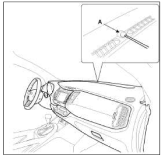
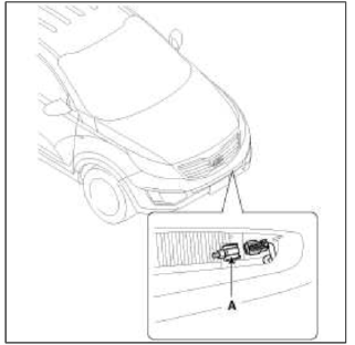
1. The photo sensor is located at the right of defrost nozzle.
2. The photo sensor contains a photovoltaic (sensitive to sunlight) diode. The solar radiation received by its light receiving portion, generates an electromotive force in proportion to the amount of radiation received which is transferred to the automatic temperature control module so that the solar radiation compensation will be performed.
Repair procedures
Inspection
1. Ignition "ON".
2. Using the scan tool.
3. Emit intensive light toward photo sensor using a lamp, and check the output voltage change.
4. The voltage will rise with higher intensive light and reduce with lower intensive light.
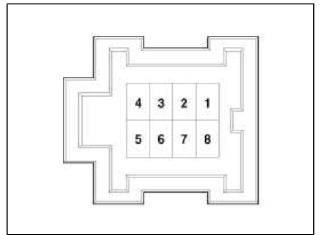
- Sensor Ground
- Photo Sensor Signal
- -
- -
- -
- DR Photo Sensor (-)
- PA Photo Sensor (-)
- 5V (Vcc)
Replacement
1. Disconnect the negative (-) battery terminal.
2. With the (-) driver, remove the photo sensor (A) from the center of defrost nozzle
3. Install in the reverse order of removal.
Ambient Sensor
Description and Operation
Description
1. The ambient temperature sensor is located at the front of the condenser and detects ambient air temperature. It is a negative type thermistor; resistance will increase with lower temperature, and decrease with higher temperatures.
2. The sensor output will be used for discharge temperature control, temperature regulation door control, blower motor level control, mix mode control and in-car humidity control.
NOTE
If the ambient temperature is below 1.0ºC (33.8ºF), the Ð/С compressor will be stopped.
The compressor will be operated by manual operating.
Repair procedures
Inspection
1. Ignition "OFF".
2. Disconnect ambient temperature sensor.
3. Check the resistance of ambient temperature sensor between terminals 1 and 2 whether it is changed by changing of the ambient temperature.
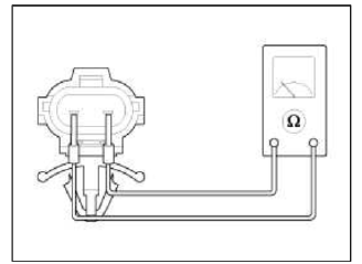
- Sensor Ground
- Ambient Sensor Signal
Specification
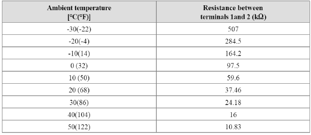
4. If the measured resistance is not specification, substitute with a known-good ambient temperature sensor and check for proper operation.
5. If the problem is collected, replace the ambient temperature sensor.
Replacement
1. Disconnect the negative (-) battery terminal.
2. Disconnect the connector and then remove the ambient temperature sensor (A).
3. Installation is the reverse order of removal.
READ NEXT:
 Cluster ionizer
Components and
Components Location
Component Location
Description and
Operation
Description
1. The function of cluster ionizer is cleaning air by sterilizing and
dissolving of air cond
SEE MORE:
Console
Components and Components Location
Components
[M/T]
Floor console assembly
Floor console tray
Console upper cover [5 speed M/T]
Console upper cover [6 speed M/T]
Console storage box mat
Console side cover [LH]
Console side cover [RH]
Console rear mounting bracket
[Ð
Using the infotainment/climate switchable controlle
NOTICE
If you install an aftermarket HID head
lamp, your vehicle's audio and electronic
device may malfunction.
Using the infotainment/climate switchable
controller
Press the button on the switchable controller
to switch between infotainment
system or climate control panel.
Press
Content
- Home
- Kia Sportage - Fifth generation (NQ5) - (2022-2026) - Owner's Manual
- Kia Sportage - Second generation (JEKM) (2005-2015) - Body Workshop Manual
- Kia Sportage Third generation (SL) - (2011-2016) - Service and Repair Manual
- Sitemap
- Top articles
