Kia Sportage: Power Window Control | Key Interlock Solenoid Control
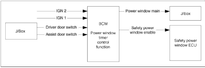
Power Window Timer Control
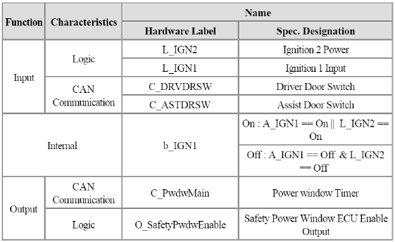
1. After IGN1 is On. Power Window can operate and after IGN1 Off it is possible to operate the Power window, for "PwdwTime"(30 sec +-3 sec).
2. During counting the PwdwTime"(30 sec +-3 sec), if Driver or Assistant side Door is open, the working the Power Window is stopped.
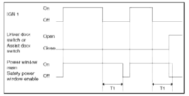
T1 : Pwdw tune (30 sec +- 3 sec)
Defogger Control
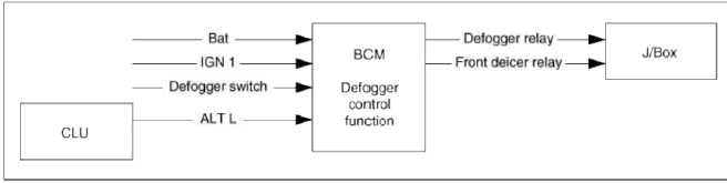
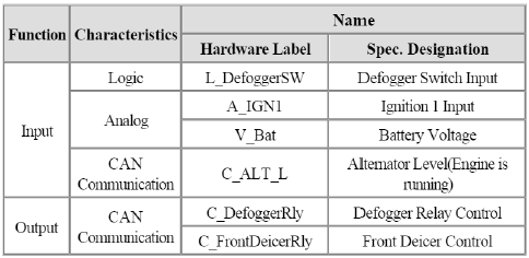
Defogger Control
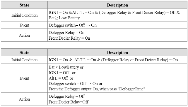
1. Defogger switch is self Return type. Therefore, when the switch is pressed, Defogger output is On and user press the Switch again, the Defogger output is Off.
2. There is no occurrence of an accident at low voltage, meaning that the Defoggers are not to be operated immediately of low voltage detection.
3. It is protected the battery from discharge.
4. State Description.
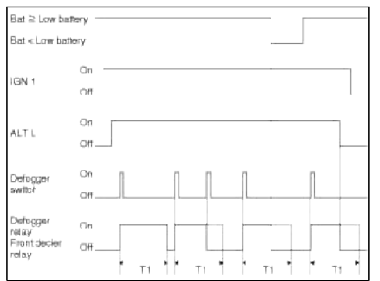
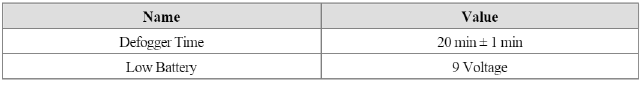
Т1 : Defogger time (20 min +- 1 min)
Key Interlock Solenoid Control
Key Interlock Solenoid Control
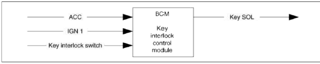
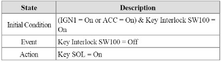
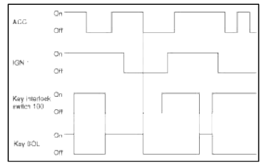
1. General Description
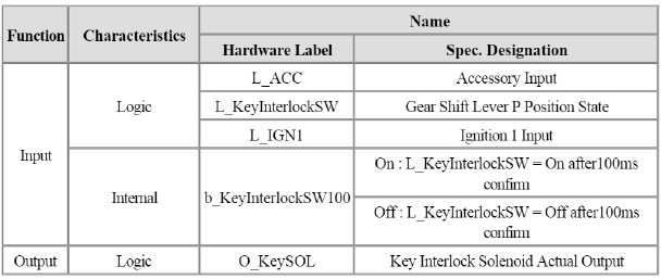
- Key Interlock Function is to check the Key Interlock Switch Input and Ignition Terminal position, and turn On or Off the key interlock solenoid.
- Key Solenoid is Pull Type.
- When IGN1 is On or ACC is On, if Key Interlock Switch is On, key interlock solenoid is Off
- When IGN1 is On or ACC is On, if Key Interlock Switch is Off, key interlock solenoid is On
- During IGN1 is Off and ACC is Off, key interlock solenoid is Off
- The internal value "b_KeyInterlockSW100" is the signal that means Key Interlock Switch value with 100 msec confirm time. So it is different from filtering time.
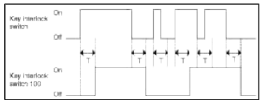
T : 100 msec
2. Go to Key Interlock OFF Condition
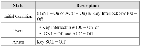
3. Go to Key Interlock ON Condition
READ NEXT:
 Repair procedures
Removal
1. Disconnect the negative (-) battery terminal.
2. Remove the crash pad lower panel.
(Refer to the BD group - "Crash pad")
3. Remove the BCM (A) after removing the nuts, conne
SEE MORE:
General Information
Specifications
Specifications
VFS: Variable Force Solenoid
Sensors
Input Speed Sensor
Type: Hall effect sensor
Specifications
Output Speed Sensor
Type: Hall effect sensor
Specifications
Oil Temperature Sensor
Type: Negative thermal coefficien
RCV Control Solenoid Valve | Canister Close Valve (CCV)
Description and Operation
Description
RCV (Recirculation Valve) Control Solenoid Valve is installed on the intercooler inlet pipe and operates the RCV actuator which controls the by-pass passage of the turbocharger compressor.
When the throttle is closed, while the engine is running at cru
Content
- Home
- Kia Sportage - Fifth generation (NQ5) - (2022-2026) - Owner's Manual
- Kia Sportage - Second generation (JEKM) (2005-2015) - Body Workshop Manual
- Kia Sportage Third generation (SL) - (2011-2016) - Service and Repair Manual
- Sitemap
- Top articles
