Kia Sportage: DBC Switch
Description and Operation
Description
The DBC function is the acronym word of Downhill Brake Control function. When a vehicle goes down the hill, just pushing the DBC switch enables the car to keep its vehicle's speed at a constant value without operating the brake pedal. The DBC function is operated when the vehicle is on the decline and its velocity is under the predetermined speed.
Repair procedures
Inspection
1. Turn ignition switch OFF and disconnect the negative (-) battery cable.
2. Remove the crash pad side switch assembly.
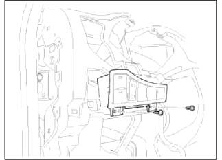
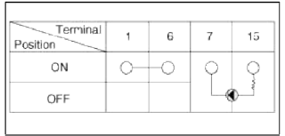
3. Check the continuity between the switch terminals as the DBC switch is engaged.
Steering Angle Sensor
Description and Operation
Description
The Steering Angle Sensor (SAS) is installed in MDPS (Motor Driven Power Steering) and it sends messages to HECU though CAN communication line.
The SAS is used to determine turning direction and speed of the steering wheel.
The HECU uses the signals from the SAS when performing ESC-related calculations.
Components (Steering Angle Sensor, Torque Sensor, Failsafe relay, etc.) of the EPS system are located inside the steering column & EPS unit assembly and the steering column & EPS runt assembly must not be disassemble to inspect or replace them. (Refer to "ST (Steering system) Gr.")
READ NEXT:
 General Information
Specifications
Specification
Tightening torque
CAUTION
Replace self-locking nuts with new ones after removal brake.
Lubricants
Special Service Tools
Special Service Tools
Front Axle Assembly
Front Hub / Knuckle / Tone Wheel
Components and
Components Location
Components
Brake disc screw
Brake disc
Hub
Hub bolt
Dust cover
Knuckle
Wheel bearing
Snap ring
Repai
SEE MORE:
Mode Control Actuator
Components and
Components Location
Component Location
Description and Operation
Description
The mode control actuator is located at the heater unit.
It adjusts position of mode door by operating mode control actuator based on
signal of Ð/С control unit. Pressing
mode s
Waterproof and rustproof
Sealing
To waterproof and rustproof the vehicle, apply sealer on assembled area of
the body panel and on any areas in
contact with the body, such as doors (inner/outer), hood (inner/outer), and tail
gate (inner/outer).
Body (Floor)
View
Section
Door
View
Section
Hood
Se
Content
- Home
- Kia Sportage - Fifth generation (NQ5) - (2022-2026) - Owner's Manual
- Kia Sportage - Second generation (JEKM) (2005-2015) - Body Workshop Manual
- Kia Sportage Third generation (SL) - (2011-2016) - Service and Repair Manual
- Sitemap
- Top articles
