Kia Sportage: Repair procedures
Removal
1. Disconnect the negative (-) battery terminal.
2. Remove the crash pad lower panel.
(Refer to the BD group - "Crash pad")
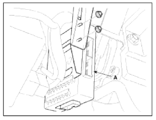
3. Remove the BCM (A) after removing the nuts, connectors and antenna cable.
Installation
1. Install the BCM after connecting the connectors and cable.
2. Install the crash pad lower panel.
3. Connect the negative (-) battery terminal.
Inspection
BCM Pin Information
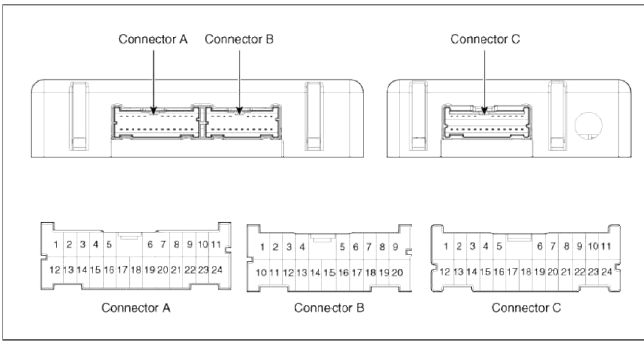
Connector A
Al Battery power supply
A2 IGN1 power supply
A3 IGN2 power supply
A4 ACC power supply
A5 Wiper Mist swtich signal
input
Ð6 Tail swtich signal input
A7 Keyin swtich signal input
A8 CrashUnlock signal input
A9 Turn Sig RH swtich signal
input
A10 Defogger swtich signal input
A11 AutoLight swtich signal input
A12 Hazard IND Power supply
A13 RPAS Power supply
A14 Rear Washer swtich signal
input
A15 Rear Wiper swtich signal
input
A16 Washer swtich signal input
A17 Wiper INT swtich signal input
A18 Rear Wiper INT swtich signal
input
A19 Hazard swtich signal input
A20 Key Interlock swtich signal
input
A21 Wiper INT Vol level signal
input
A22 Turn Sig LH swtich signal
input
A23 RPAS Off swtich signal input
A24 GND
Connector B
B1 Head Lamp High swtich signal
input
B2 Head Lamp Low swtich signal
input
B3 Hazard IND control
B4 К-Line communication
B5 LIN_RCR Sensor Status
output
Ð’6 AutoLight Power supply
B7 CAN HIGH
B8 AutoLight Sensor level signal
input
B9 RPAS Off IND control
B10 Front Fog swtich signal input
B11 Rear Fog swtich signal input
B12 LIN_BackUpSiren output
Ð’13 LIN_RL Sensor Status output
B14 RPAS power GND
B15 LIN_RCL Sensor Status
output
B16 LIN_RR Sensor Status output
B17 -
B18 CAN_LOW
B19 AutoLight power GND
B20 Head LampLow signal output
Connector C
C1 RR SeatBelt IND control
C2 RC SeatBelt IND control
C3 AST SeatBelt IND control
C4 Key SOL output
C5 RoomLamp output
C6 TumSig FLH output
C7 TumSig FRH output
C8 TumSig RLH output
C9 TumSig RRH output
C10 Battery power supply
C11 Battery power supply
C12 GND
C13 RL SeatBet IND control
C14 AVTail output
C15 Door Unlock signal control (to
NAVI)
C16 Safety P/window Enable control
C17 RPAS warning Buzzer output
C18 Key Hole Illum output
C19 HeadLamp Washer Relay
output
C20 Wiper Relay output
C21 Cornering Lamp RH output
C22 Cornering Lamp LH output
C23 Rear Fog Relay output
C24 Horn output control
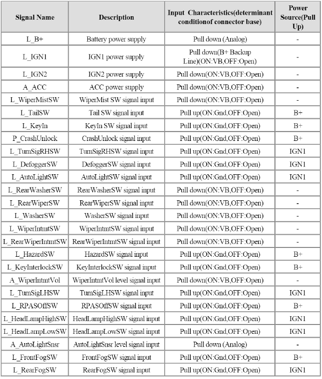
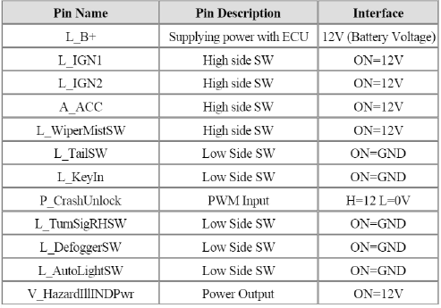
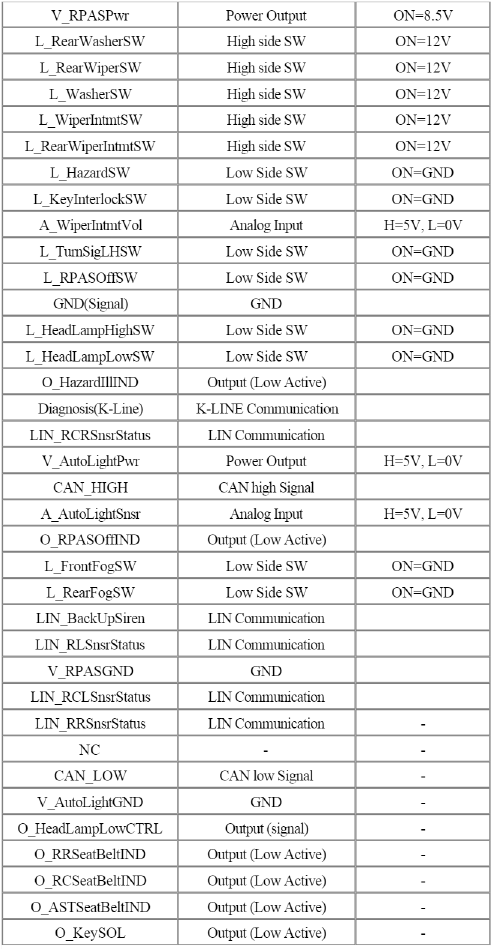
Inputs Description and Characteristics
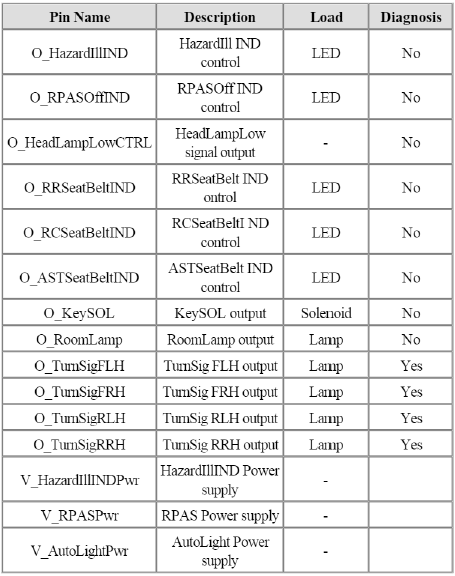
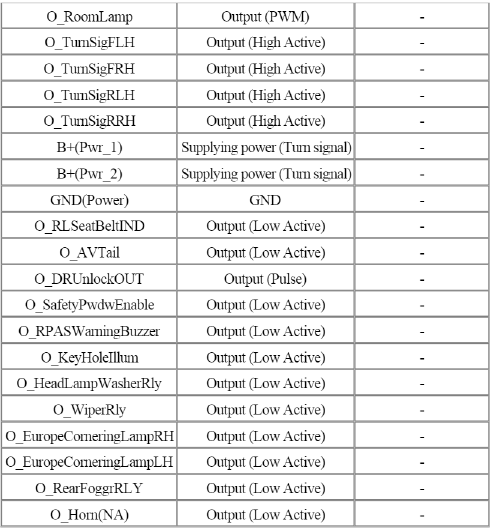
Outputs Description and Characteristics
Module Interface Description and Characteristics
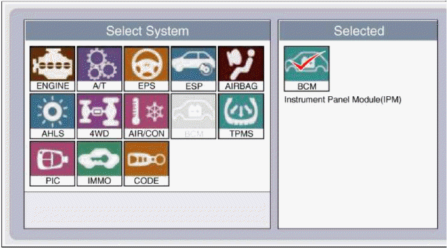
Trouble Diagnostics When Using GDS
1. The BCM can be diagnosed by using the GDS. The BCM communicates with the GDS which then displays inputs and outputs along with codes.
2. To diagnose the BCM function, select the vehicle model and BCM.
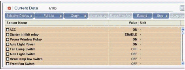
3. To consult the present input/out value of BCM, "Current DATA". It provides information of BCM input/output conditions of power supply, turn signal/brake lamp, headlamp, door locks, outside mirror, wiper, auto-light and transmitters etc.
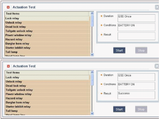
4. To perform functional test on BCM outputs, select "Actuation Test".
READ NEXT:
 Components and Components Location | Power Seat Motor | Power Seat Control Switch | Seat Heater Switch
Component Location
Slide motor
Rear height motor
Reclining motor
Power seat switch
Reclining switch
SEE MORE:
Risk of burns when parking or stopping vehicle
Vehicle handling instructions
Do not park or stop the vehicle near
flammable items such as leaves,
paper, oil, and tire. Such items placed
near the exhaust system can become
a fire hazard.
When an engine idles at a high speed
with the rear side of the vehicle touching
the wall, hea
Rail Pressure Sensor (RPS)
Description and Operation
Description
Rail Pressure Sensor (RPS) is installed on the delivery pipe and measures the
instantaneous fuel pressure in the delivery pipe. The sensing element
(Semiconductor element) built in the sensor converts the pressure to voltage
signal. By using this si
Content
- Home
- Kia Sportage - Fifth generation (NQ5) - (2022-2026) - Owner's Manual
- Kia Sportage - Second generation (JEKM) (2005-2015) - Body Workshop Manual
- Kia Sportage Third generation (SL) - (2011-2016) - Service and Repair Manual
- Sitemap
- Top articles
