Kia Sportage: Pressure Sensor
Description and Operation
Description
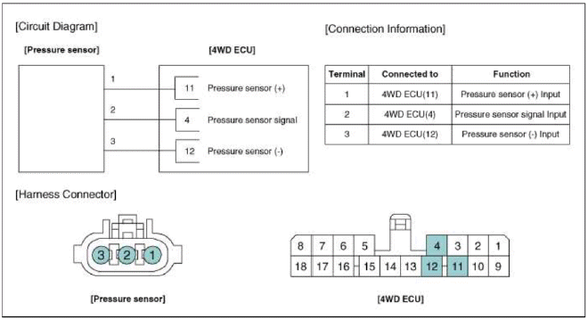
The 4WD ECU makes a Motor Pump (Actuator) turn round for generating an oil pressure. And then it presses a multiple disk clutch and transfers the generated torque into rear wheels. Its torque value varies according to a pressure status.
Schematic Diagrams
Circuit Diagram
Repair procedures
Inspection
NOTE
If you have trouble code related to the pressure sensor (P1825, P1826, P1827, P1828), check pressure sensor according to the inspection process.
Pressure Sensor Inspection Procedure
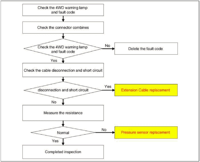
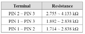
Measure the resistance of pressure sensor
1. Turn ignition switch OFF.
2. Disconnect the pressure sensor connector.
3. Measure resistance between sensor terminal and terminal.
4. Check the measured resistance. (Refer to table)
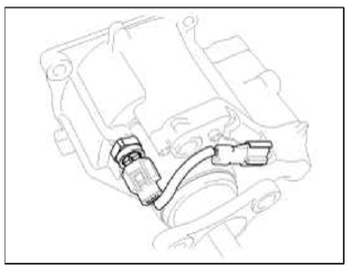
Removal
1. Remove the coupling assembly. (Refer to "coupling assembly" in 4WD group)
2. Remove the extension Cable (A).
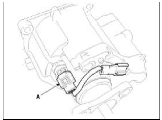
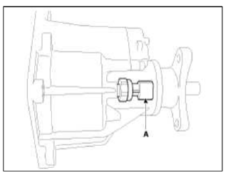
3. Remove the pressure sensor (A) with 24mm socket.
CAUTION
- Keep going horizontal state to prevent leaks during remove the pressure sensor.
Tightening torque: 7.8 ~ 9.8 N.m (0.8 ~ l.0 kgf.m, 5.8 ~ 7.2 lb-ft)
Installation
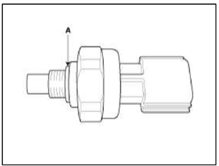
CAUTION
- Check the cleanliness of the pressure sensor before installation.
- Check the pressure sensor О-ring (A).
1. Installation is the reverse of removal.
READ NEXT:
 General Information
Specifications
Specifications
VFS: Variable Force Solenoid
Sensors
Input Speed Sensor
Type: Hall effect sensor
Specifications
Output Speed Sensor
Type: Hall effe
SEE MORE:
Repair procedures | Components and Components Location
Component Replacement After Deployment
NOTE
Before doing any SRS repairs, use the GDS Pro to check for DTCs. Refer to the Diagnostic Trouble Code list for repairing of the related DTCs.
When the front airbag(s) deployed after a collision, replace the following items.
SRSCM
Deployed
Transaxle Oil Temperature Sensor
Description and Operation
Description
Transaxle oil temperature sensor monitors the automatic transaxle fluid's
temperature and conveys the readings to
TCM. It is an NTC (Negative Thermal Coefficient) sensor whose resistance has an
inversely proportional
relationship with the tempe
Content
- Home
- Kia Sportage - Fifth generation (NQ5) - (2022-2026) - Owner's Manual
- Kia Sportage - Second generation (JEKM) (2005-2015) - Body Workshop Manual
- Kia Sportage Third generation (SL) - (2011-2016) - Service and Repair Manual
- Sitemap
- Top articles
