Kia Sportage: Repair procedures | Components and Components Location
Component Replacement After Deployment
NOTE
Before doing any SRS repairs, use the GDS Pro to check for DTCs. Refer to the Diagnostic Trouble Code list for repairing of the related DTCs.
When the front airbag(s) deployed after a collision, replace the following items.
- SRSCM
- Deployed airbag(s)
- Seat belt pretensioner(s)
- Front impact sensors
- SRS wiring harnesses
- Inspect the clock spring for heat damage.
If any damage found, replace the clock spring.
When the side/curtain airbag(s) deployed after a collision, replace the following items.
- SRSCM
- Deployed airbag(s)
- Side impact sensor(s) for the deployed side(s)
- SRS wiring harnesses
After the vehicle is completely repaired, confirm the SRS airbag system is OK.
- Turn the ignition switch ON; the SRS indicator should come on for about six seconds and then go off.
Components and Components Location
Components
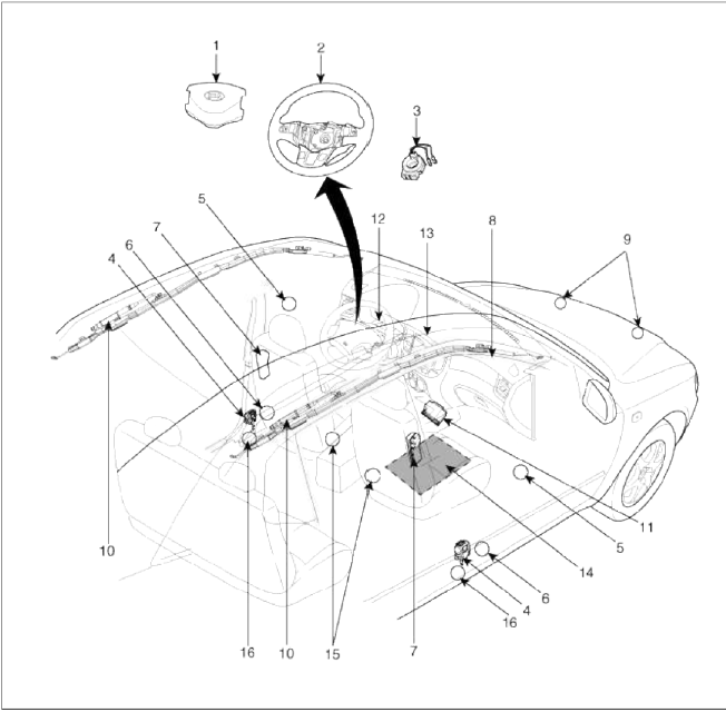
- Driver Airbag (DAB)
- Steering Wheel
- Clock Spring
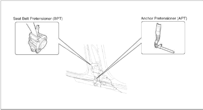
- Seat Belt Pretensioner (BPT)
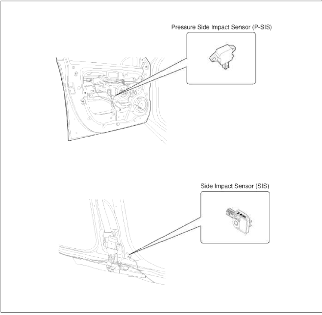
- Pressure Side Impact Sensor (P-SIS)
- Side Impact Sensor (SIS)
- Side Airbag (SAB)
- Passenger Airbag (PAB)
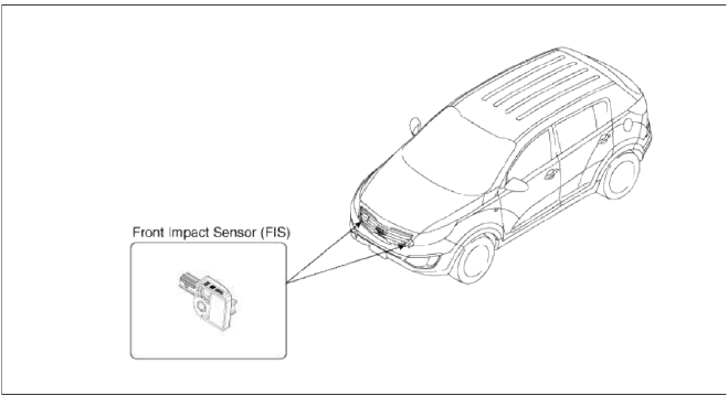
- Front Impact Sensor (FIS)
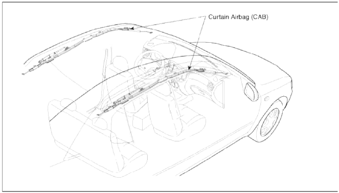
- Curtain Airbag (CAB)
- Supplemental Restraint System Control Module (SRSCM)
- Airbag Warning Lamp
- Telltale Lamp
- Passenger Occupant Detecting System (PODS)
- Belt Tension Sensor
- Anchor Pretensioner (APT)
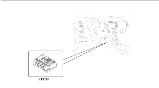
Components Location
Supplemental Restraint System Control Module (SRSCM)
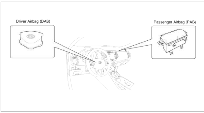
Driver Airbag (DAB) / Passenger Airbag (PAB)
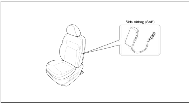
Side Airbag (SAB)
Curtain Airbag (CAB)
Seat Belt Pretensioner (BPT)/ Anchor Pretensioner (APT)
Front Impact Sensor (FIS)
Side Impact Sensor (SIS)
READ NEXT:
 SRS Control Module (SRSCM)
Description and Operation
Description
The primary purpose of the SRSCM (Supplemental Restraints System Control
Module) is to discriminate between
an event that warrants restraint system dep
SEE MORE:
Side Airbag (SAB) Module | Curtain Airbag (CAB) Module
Description and Operation
Description
The Side Airbags (SAB) are installed inside the front seat and protects the driver and passenger from danger when side crash occurs. The SRSCM determines deployment of side airbag by using Side Impact Sensor (SIS) signal.
CAUTION
Never attempt to mea
Closing the liftgate
To close the liftgate, lower and push
down the liftgate firmly. Make sure
that the liftgate is securely latched.
WARNING
Make sure your hands, feet and other
parts of your body are safely out of the
way before closing the liftgate.
WARNING
Exhaust fumes
The liftgate lid should be
Content
- Home
- Kia Sportage - Fifth generation (NQ5) - (2022-2026) - Owner's Manual
- Kia Sportage - Second generation (JEKM) (2005-2015) - Body Workshop Manual
- Kia Sportage Third generation (SL) - (2011-2016) - Service and Repair Manual
- Sitemap
- Top articles
