Kia Sportage: General Information | Front Body
General
1. Basically, all measurements in this manual are taken with a tracking gauge.
2. When a measuring tape is used, check to be sure there is no elongation, twisting or bending.
3. For measuring dimensions, both projected dimension and actual-measurement dimension are used in this manual
Measurement Method
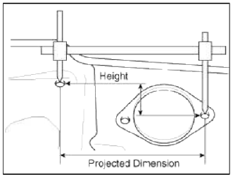
Projected Dimensions
1. These are the dimensions measured when the measurement points are projected into the reference plane, and are the reference dimensions used for body alterations.
2. If the length of the tracking gauge probes is adjustable, make the measurement by lengthening one probe by the amount equivalent to the difference in height of the two surfaces.
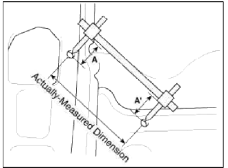
Actual-Measurement Dimensions
1. These dimensions indicate the actual linear distance between measurement points, and are the reference dimensions for use if a tracking gauge is used for measurement.
2. Measure by first adjusting both probes to the same length (A=A').
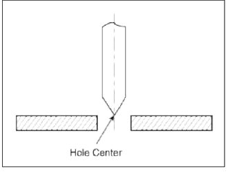
Measurement Point
1. Measurements should be taken at the hole center.
Front Body
Body Repair
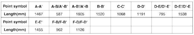
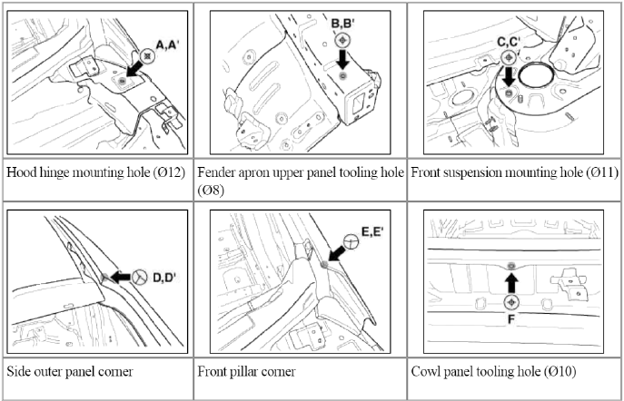
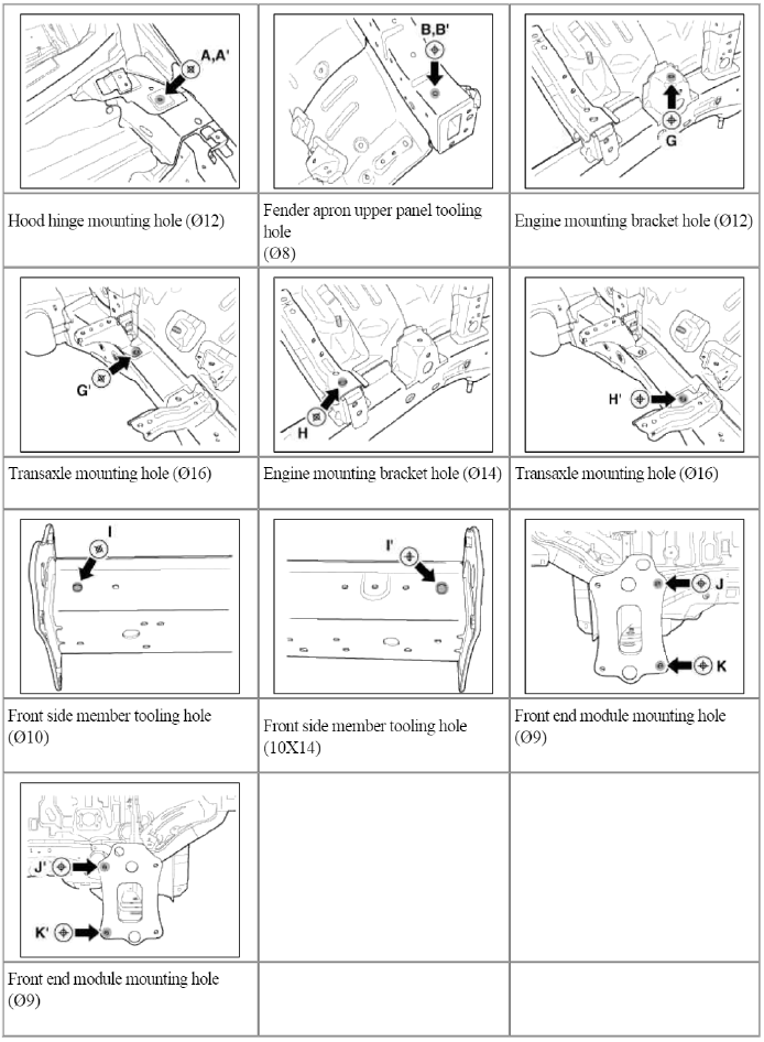
Front Body A
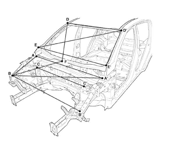
* These dimensions indicated in this figure are actual-measurement dimensions.
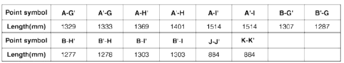
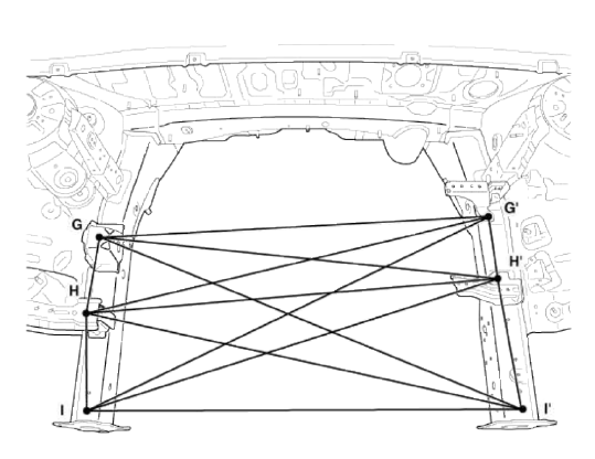
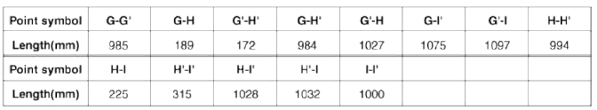
Front Body Ð’
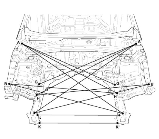
* These dimensions indicated in this figure are actual-measurement dimensions.
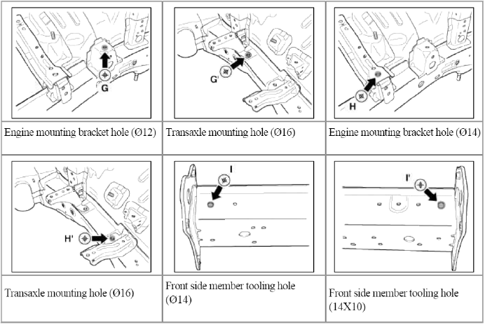
Front Body C
* These dimensions indicated in this figure are actual-measurement dimensions.
READ NEXT:
 Side Body | Interior
Body Repair
Side Body A
* These dimensions indicated in this figure are actual-measurement dimensions.
Side Body Ð’
* These dimensions indicated in this figure are actu
SEE MORE:
Adjustment - Repair procedures
Adjustment
Parking Brake Shoe Clearance Adjustment [2WD]
1. Raise the vehicle, and make sure it is securely supported.
2. Remove the rear tire and wheel.
3. Remove the plug from the disc.
4. Rotate the toothed wheel of adjuster by a screw driver until the disc is not
moving, and then retu
Owner maintenance
The following lists are vehicle checks
and inspections that should be performed
by the owner or an authorized
Kia dealer at the frequencies indicated
to help ensure safe, dependable operation
of your vehicle.
Any adverse conditions should be
brought to the attention of your dealer
as soon
Content
- Home
- Kia Sportage - Fifth generation (NQ5) - (2022-2026) - Owner's Manual
- Kia Sportage - Second generation (JEKM) (2005-2015) - Body Workshop Manual
- Kia Sportage Third generation (SL) - (2011-2016) - Service and Repair Manual
- Sitemap
- Top articles
