Kia Sportage: Repair procedures
Refrigerant System Service Basics
Refrigerant Recovery
Use only service equipment that is U.L-listed and is certified to meet the requirements of SAE J2210 to remove 4FC-134a(R-134a) from the air conditioning system.
CAUTION
- Air conditioning refrigerant or lubricant vapor can irritate your eyes, nose, or throat.
- Be careful when connecting service equipment.
- Do not breathe refrigerant or vapor.
If accidental system discharge occurs, ventilate work area before resume of service.
Additional health and safety information may be obtained from the refrigerant and lubricant manufacturers.
1. Connect an R-134a refrigerant Recovery/Recycling/Charging System (A) to the high-pressure service port (B) and the low-pressure service port (C) as shown, following the equipment manufacturer's instructions.
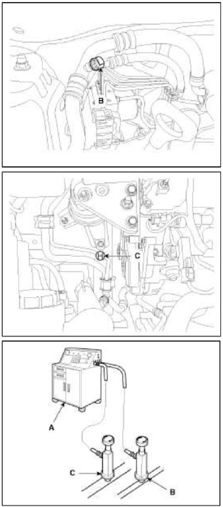
2. Measure the amount of refrigerant oil removed from the Ð/С system after the recovery process is completed. Be sure to install the same amount of new refrigerant oil back into the Ð/С system before charging.
System Evacuation
Use only service equipment that is U.L-listed and is certified to meet the requirements of SAE J2210 to remove HEC-134a(R-134a) from the air conditioning system.
CAUTION
- Air conditioning refrigerant or lubricant vapor can irritate your eyes, nose, or throat.
- Be careful when connecting service equipment.
- Do not breathe refrigerant or vapor.
If accidental system discharge occurs, ventilate work area before resume of service.
Additional health and safety information may be obtained from the refrigerant and lubricant manufacturers.
1. When an Ð/С System has been opened to the atmosphere, such as during installation or repair, it must be evacuated using an R-134a refrigerant Recovery/Recycling/Charging System. (If the system has been open for several days, the receiver/dryer should be replaced, and the system should be evacuated for several hours.)
2. Connect an R-134a refrigerant Recovery/Recycling/Charging System (A) to the high-pressure service port (B) and the low-pressure service port (C) as shown, following the equipment manufacturer's instructions.
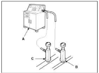
3. If the low-pressure does not reach more than 93.3 kPa (700 mmHg, 27.6 in.Hg) in 10 minutes, there is probably a leak in the system. Partially charge the system, and check for leaks (see Leak Test.).
4. Remove the low pressure valve from the low-pressure service port.
System Charging
Use only service equipment that is U.L-listed and is certified to meet the requirements of SAE J2210 to remove 4FC-134a(R-134a) from the air conditioning system.
CAUTION
- Air conditioning refrigerant or lubricant vapor can irritate your eyes. nose, or throat.
- Be careful when connecting service equipment.
- Do not breathe refrigerant or vapor.
If accidental system discharge occurs, ventilate work area before resume of service.
Additional health and safety information may be obtained from the refrigerant and lubricant manufacturers.
1. Connect an R-134a refrigerant Recovery/Recycling/Charging System (A) to the high-pressure service port (B) as shown, following the equipment manufacturer's instructions.
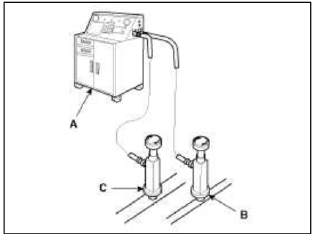
2. Add the same amount of new refrigerant oil to system that was removed during recovery. Use only specified refrigerant oil. Charge the system with 18.0 +- 0.88 oz. (510 +- 25g) of R-134a refrigerant. Do not overcharge the system the compressor will be damaged.
Refrigerant Leak Test
Always conduct a leak test with an electronic leak detector whenever leakage or refrigerant is suspected and when conducting service operations which are accompanied by disassembly or loosening or connection fittings.
NOTE
In order to use the leak detector properly, read the manual supplied by the manufacturer.
If a gas leak is detected, proceed as follows:
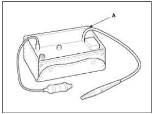
1. Check the torque on the connection fittings and, if too loose, tighten to the proper torque. Check for gas leakage with a leak detector (A).
2. If leakage continues even after the fitting has been tightened, discharge the refrigerant from the system, disconnect the fittings, and check then seating faces for damage. Always replace, even if the damage is slight.
3. Check the compressor oil and add oil if required.
4. Charge the system and recheck for gas leaks. If no leaks are found, evacuate and charge the system again.
READ NEXT:
 Components and Components Location | Compressor Oil
Component Location Index
Engine Room
Condenser
Receiver-drier
Compressor
Expansion Valve
Service port (High)
Service port (Low)
Ð/С Pressure
Tr
Refrigerant line | Compressor
Components and Components Location
Component Location
Repair procedures
Replacement
1. Discharge refrigerant from refrigeration system.
2. Replace faulty tube or hose.
CAUTION
Cap the o
SEE MORE:
Photo Sensor | Ambient Sensor
Description and Operation
Description
1. The photo sensor is located at the right of defrost nozzle.
2. The photo sensor contains a photovoltaic (sensitive to sunlight) diode. The solar radiation received by its light receiving portion, generates an electromotive force in proportion to the amoun
Blind-Spot Collision-Avoidance Assist (BCA)
Blind-Spot Collision-Avoidance Assist (BCA) (if equipped)
Blind-Spot Collision-Avoidance Assist is
designed to help detect and monitor
approaching vehicles in the driver's blind
spot area and warn the driver of a possible
collision with a warning message and
audible warning.
In addition
Content
- Home
- Kia Sportage - Fifth generation (NQ5) - (2022-2026) - Owner's Manual
- Kia Sportage - Second generation (JEKM) (2005-2015) - Body Workshop Manual
- Kia Sportage Third generation (SL) - (2011-2016) - Service and Repair Manual
- Sitemap
- Top articles
