Kia Sportage: Seat Belt Buckle Switch (BS) | Passive Occupant Detection System (PODS)
Description and Operation
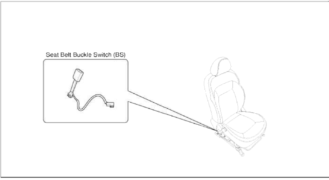
Description
The SRSCM shall monitor the status of the driver and front passenger seat belt buckle. The SRSCM provides one pin each for the driver and front passenger seat belt buckle status input. The seat belt buckle circuit operates from internal boost voltage supplied by the SRSCM, and uses chassis ground for the signal return. The buckle status shall modify the SRSCM deployment. If the buckle status is unbuckled, the corresponding pretensioner will not be deactivated.
Components and Components Location
Components
Repair procedures
Removal
1. Disconnect the battery negative cable, and wait for at least three minutes before beginning work.
2. Remove the front seat assembly. (Refer to the Body group- Front seat)
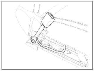
3. Loosen the seat belt buckle mounting bolt and remove the seat belt buckle switch.
Installation
CAUTION
Be sure to install the harness wires not to be pinched or interfered with other parts.
1. Remove the ignition key from the vehicle.
2. Disconnect the battery negative cable, and wait for at least three minutes before beginning work.
3. Install the seat belt buckle switch.
Tightening Torque: 39.2 ~ 53.9 N.m (4.0 ~ 5.5 kgf.m, 28.9 ~ 39.8 lb-ft)
4. Install the front seat assembly. (Refer to the Body group-Front seat)
5. Reconnect the battery negative cable.
6. After installing the seat belt buckle switch, confirm proper system operation:
- Тurn the ignition switch ON: the SRS indicator should be turned on for about six seconds and then go off.
Passive Occupant Detection System (PODS)
Description and Operation
Description
The system is intended to classify the occupancy status of the front passenger seat in a motor vehicle based upon the measured force on the bottom seat cushion.
The system also communicates to the SRSCM whether to allow or inhibit the deployment of the passenger air bags and/or pretensioner based upon this status.
The System also measured dynamic responses of the occupant. This information is used to identify when a child seat is cinched down tightly with the seat belt, and to also determine if the seat is unoccupied.
However, the dynamic measurements are not intended, nor capable of monitoring the seating position of the occupant, nor can they determine the proximity of the occupant to the inflator modules.
The system should not be confused with an occupant position recognition system, or any other occupant proximity sensor.
The Passive Occupant Detection System (PODS) utilizes bladder placed between the passenger seat cushion and suspension to measure the occupant's loading force on the passenger seat. The sensor mat is connected to smart digital pressure sensor which is mounted under the seat pan. The quantitative force determined by the system is compared to a given threshold for determination of passenger airbag suppression.
Components and Components Location
Components
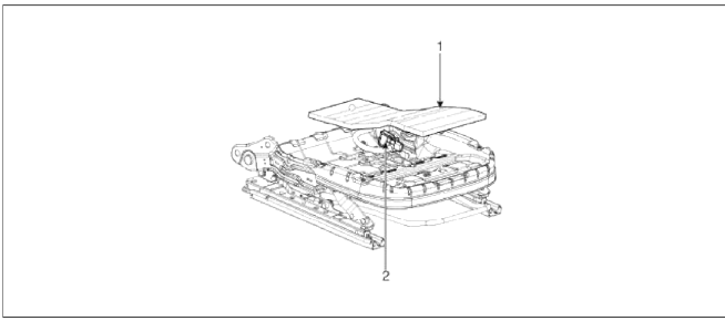
- Sensor mat
- PODS Unit
Repair procedures
Removal
1. Disconnect the battery negative cable, and wait for at least three minutes before beginning work.
2. Remove the front passenger seat assembly. (Refer to the Body group - Seat)
3. Remove the seat cushion as an assembly. (Refer to the Body group - Seat)
Installation
1. Install the PODS equipped seat cushion assembly.
(Refer to the Body group - Seat)
2. Install the front passenger seat assembly.
(Refer to the Body group - seat)
3. Reconnect the battery negative cable.
4. After installing the PODS, confirm proper system operation:
- Тurn the ignition switch ON: the SRS indicator should be turned on for about six seconds and then go off.
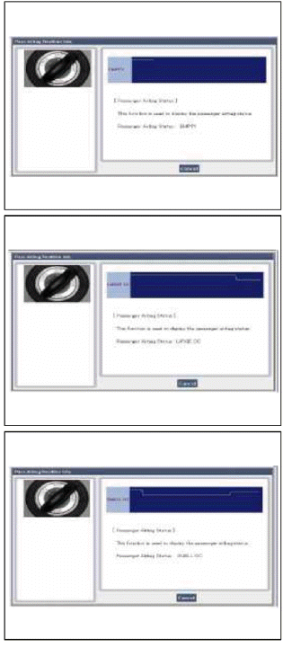
Telltale lamp will nun on for 4 seconds and be turned off for 3 seconds. After the 7 seconds, it shall remain off if the PODS does not require suppression and the passenger airbag is enabled.
NOTE
Be sure to perform PODS reset with scan tool after replacing PODS equipped seat cushion.
PODS Re-zero procedure
You should perform PODS Re-zero procedure after service or replacement about all part of the passenger seat.
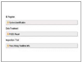
1. Ignition "OFF", connect GDS.
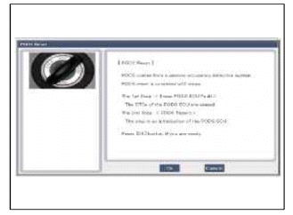
2. Ignition "ON" & Engine "OFF", select Airbag system and "PODS Reset" mode.
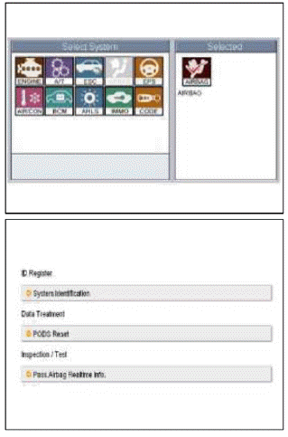
3. The GDS will show the two PODS RESET function steps.
- Erase PODS diagnostic codes.
- PODS initialization.
CAUTION
This step must be done PODS re-zero, when the front passenger seat is empty.
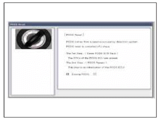
4. Press the OK button to erase the PODS related diagnostic codes.
5. Press OK button to initialize the PODS.
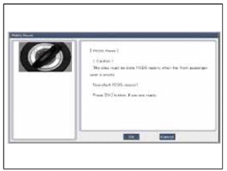
CAUTION
This step must be done PODS re-zero, when the front passenger seat is empty.
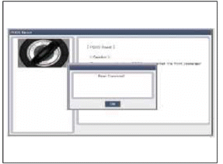
6. The PODS initialization procedure will be performed.
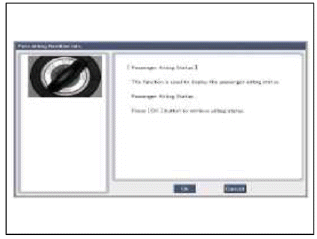
7. Check PODS situation with selecting" Pass. Airbag Real time Info" after performing PODS Reset procedure.
8. Perform inspection with pressing OK button.
9. Finish the procedure with pressing cancel button if there is no problem after inspecting each status as below.
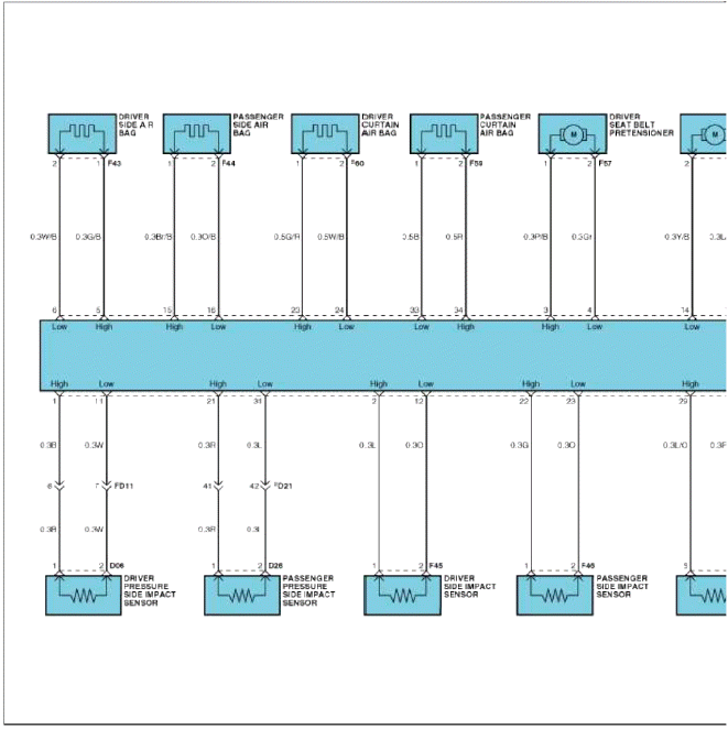
Schematic Diagrams
Circuit Diagram (1)
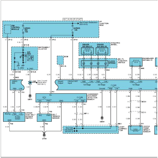
Circuit Diagram (2)
Harness Connector
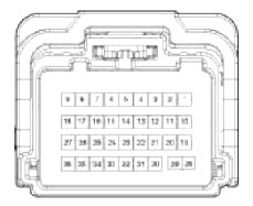 Connector A
- Ignition
- -
- Airbag warning lamp
- (1st stage) Driver airbag High
- (1st stage) Driver airbag Low
- -
- -
- Front impact sensor [Driver] High
- CAN_High
- -
- -
- Telltale warning lamp
- (1st stage) Passenger airbag High
- (1st stage) Passenger airbag Low
- -
- -
- Front impact sensor [Driver] Low
- CAN_Low
- Ground
- -
- Crash Output
- (2nd stage) Driver airbag High
- (2nd stage) Driver airbag Low
- -
- -
- Front impact sensor [Passenger] High
- -
- -
- -
- Seat belt reminder interface [Passenger]
- (2nd stage) Passenger airbag High
- (2nd stage) Passenger airbag Low
- -
- -
- Front impact sensor [Passenger] Low
- -
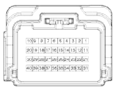 Connector B
- Pressure side impact sensor [Driver] High
- Side impact sensor [Driver] High
- Seat belt pretensioner [Driver] High
- Seat belt pretensioner [Driver] Low
- Side airbag [Driver] High
- Side airbag [Driver] Low
- -
- -
- -
- -
- Pressure side impact sensor [Driver] Low
- Side impact sensor [Driver] Low
- Seat belt pretensioner [Passenger] High
- Seat belt pretensioner [Passenger] Low
- Side airbag [Passenger] High
- Side airbag [Passenger] Low
- -
- -
- -
- -
- Pressure side impact sensor [Passenger] High
- Side impact sensor [Passenger] High
- Curtain airbag [Driver] High
- Curtain airbag [Driver] Low
- Anchor pretensioner [Driver] High
- Anchor pretensioner [Driver] Low
- -
- -
- Seat buckle switch [Passenger] High
- Seat buckle switch [Passenger] Low
- Pressure side impact sensor [Passenger] Low
- Side impact sensor [Passenger] Low
- Curtain air bag [Passenger] High
- Curtain airbag [Passenger] Low
- Anchor pretensioner [Passenger] High
- Anchor pretensioner [Passenger] Low
- -
- -
- Seat buckle switch [Driver] High
- Seat buckle switch [Driver] Low
READ NEXT:
 Driver Airbag (DAB) Module and Clock Spring
Description and
Operation
Description
Driver Airbag (DAB) is installed in the steering wheel and electrically
connected to SRSCM via the clock spring. It
protects the driver by deploying t
SEE MORE:
Defroster
The vehicle is equipped with a defroster
for removing frost or fog from the rear
window.
CAUTION
Conductors
To prevent damage to the conductors
bonded to the inside surface of the rear
window, never use sharp instruments or
window cleaners containing abrasives to
clean the window.
If you w
Repair procedures
Inspection
Check it by the procedure below to see if the function of the ECM is normal.
1. Turn the ignition key to the "ON" position.
2. Cover the forward facing sensor.
3. Head a light to the rearward looking sensor.
4. The ECM should be darkened as soon as the rearward lo
Content
- Home
- Kia Sportage - Fifth generation (NQ5) - (2022-2026) - Owner's Manual
- Kia Sportage - Second generation (JEKM) (2005-2015) - Body Workshop Manual
- Kia Sportage Third generation (SL) - (2011-2016) - Service and Repair Manual
- Sitemap
- Top articles
