Kia Sportage: Shift Lever
Components and Components Location
Components
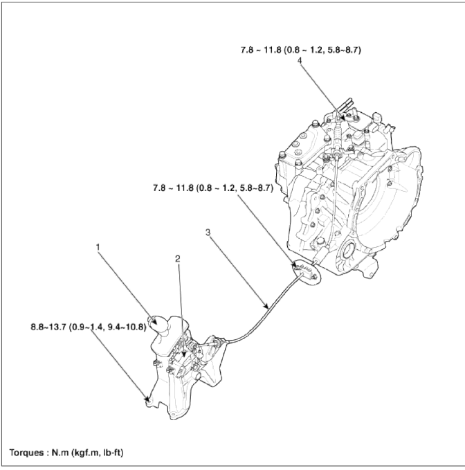
- Shift lever knob & boots assembly
- Shift lever assembly
- Control cable assembly
- Manual control lever (T/M side)
Repair procedures
Removal
Shift Lever Assembly Replacement
1. Remove the center console assembly. (Refer to "Interior (console)" in BD group.)
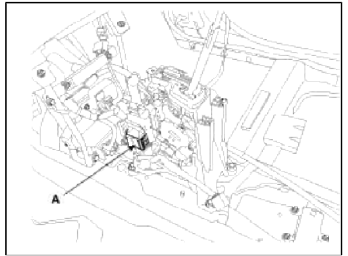
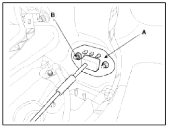
2. Disconnect sports mode connector (A).
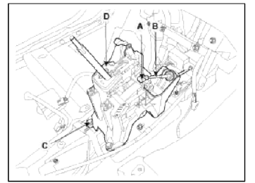
3. Take off the clip (A) and then remove the shift cable (B).
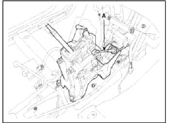
4. Remove the shift lever assembly (D) by removing the bolts (C-4ea).
Tightening torque: 8.8 ~ 13.7 N.m (0.9 ~ 1.4 kgf.m, 6.5 ~ 10.1 lb-ft)
5. Installation is the reverse of removal.
NOTE
Make sure vehicle does not roll before setting room side shift lever and T/M side manual control lever to "N" position.
Control Cable Replacement
1. Remove the center console assembly. (Refer to "Interior (console)" in BD group.)
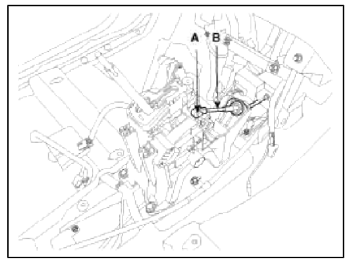
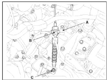
2. Take off the clip (A) and then remove the control cable (B).
3. Remove the control cable assembly in the vehicle after removing the nuts (B) and the retainer (A).
Tightening torque: 7.8 ~ 11.8 N.m (0.8 ~ 1.2 kgf.m, 5.8 ~ 8.7 lb-ft)
4. Remove the nut (C).
5. Remove the cable (B) from the bracket (A) at transaxle assembly side (Refer to "Automatic Transaxle" in this group).
6. Remove the control cable inside of cab.
Inspection
1. Check the damage and operation of the control cable.
2. Check the damage of the boot.
3. Check the damage and corrosion of the bushing.
4. Check the damage or weakening of the spring.
Installation
1. Installation is the reverse of removal.
NOTE
Make sure vehicle does not roll before setting room side shift lever and T/M side manual control lever to "N" position.
Adjustment
Adjusting method for T/M control cable
1. Make sure vehicle does not roll before setting room side shift lever and T/M side manual control lever to "N" position.
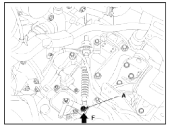
2. Connect room side shift lever and control cable (A).
3. Push cable to "F" direction shown to eliminate FREE PLAY.
4. Tighten adjusting nut (A).
Tightening torque: 7.8 ~ 11.8 N.m (0.8 ~ 1.2 kgf.m, 5.8 ~ 8.7 lb-ft)
5. After adjusting, check to be sure that this part operates as designed at each range of T/M side corresponding to each position of room lever.
READ NEXT:
 General Information
Specifications
Specifications
Tightening Torque
Special Service Tools
Special Tools
Troubleshooting
Troubleshooting
SEE MORE:
Rear Seat Belt
Repair procedures
Replacement
Rear Seat Belt Replacement
CAUTION
When installing the belt, make sure not to damaged the retractor.
1. Remove the following items first.
Rear seat assembly
(Refer to the BD group - "Rear Seat")
Front door scuff trim & Rear door scu
AUTO HOLD
The Auto Hold is designed to maintain
the vehicle in a standstill even though
the brake pedal is not pressed after the
driver brings the vehicle to a complete
stop by pressing the brake pedal.
Applying Auto Hold function
Press the brake pedal and start the
vehicle.
Press the Auto Hold b
Content
- Home
- Kia Sportage - Fifth generation (NQ5) - (2022-2026) - Owner's Manual
- Kia Sportage - Second generation (JEKM) (2005-2015) - Body Workshop Manual
- Kia Sportage Third generation (SL) - (2011-2016) - Service and Repair Manual
- Sitemap
- Top articles
