Kia Sportage: Specifications, Components and Components Location, Description and Operation | Auto Light Sensor
Specifications
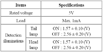
Specifications
Components and Components Location
Component Location
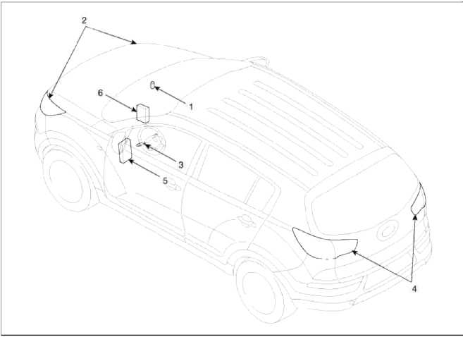
- Auto light sensor
- Head lamps
- Lighting switch (Auto)
- Tail lamps
- SJB (Smart Junction Box)
- BCM (Body Control Module)
Schematic Diagrams
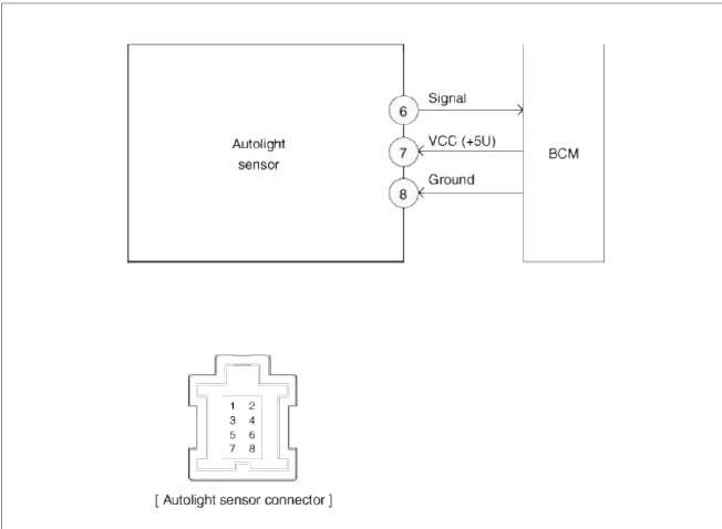
Circuit Diagram
-
Photo signal (+)
-
-
Photo signal, RH (-)
-
-
Photo signal, LH (-)
-
Signal
-
VCC (+5V)
-
Ground
Description and Operation
Description
This function describes the following features
- Input detection by Auto Light Sensor.
- Generate Auto Light Out Status data.
- Send Auto Light Out Status.
- Tail Lamp Control by Auto light Mode.
- Head Lamp Low Control by Auto light Mode.
- AV Tail Control by Auto Light sensor level.
- Auto Light Mode State Diagram is based on Auto Light Sensor's level.
- Power condition of Auto Light Action
- When ACC, IGN, START terminal states, Auto Light Sensor operates.
Auto Light Sensor
Repair procedures
Inspection
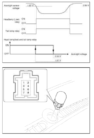
In the state of IGN1 ON, when multi function switch module detects auto light switch on, tail lamp relay output and head lamp low relay output are controlled according to auto light sensor's input.
The auto light control doesn't work if the pin sunlight supply (5V regulated power from Ignition 1 power to sunlight sensor) is in short circuit with the ground.
If IGN1 ON, The IPM monitors the range of this supply and raises up a failure as soon as the supply's voltage is out of range. Then this failure occurs and as long as this is present, the head lamp must be turned on without taking care about the sunlight level provided by the sensor.
This is designed to prevent any head lamp cut off when the failure occurs during the night.
Removal
1. Disconnect the negative (-) battery terminal.
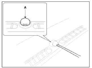
2. Remove the photo & auto light sensor (A) from crash pad upper side by using a flat-up screwdriver.
3. Remove the auto light sensor connector.
Installation
1. Reconnect the auto light sensor connector.
2. Install the auto light sensor.
READ NEXT:
 Schematic Diagrams, Description and Operation
Schematic Diagrams
Circuit Diagram
Description and Operation
Description
The immobilizer system will disable the vehicle unless the proper ignition
key is used, in addition to the
SEE MORE:
Operating front fog light
Operating front fog light (if equipped)
Fog lights are designed to provide
improved visibility when visibility is poor
due to fog, rain or snow, etc.
The fog lights will turn on when the fog
light switch (1) is turned to the on position
after the headlamp is turned on.
To turn off the f
Exterior Lighting Control
Tail Lamp Control
1. This function describes the following features
Turn on and off Tail Lamp by switch input.
Turn on and off Tail Lamp in Auto Light Control command.
Automatically cut off Tail Lamps if a driver forgets to turn them off.
Output control of Tail Lamp.
2. Tail Auto
Content
- Home
- Kia Sportage - Fifth generation (NQ5) - (2022-2026) - Owner's Manual
- Kia Sportage - Second generation (JEKM) (2005-2015) - Body Workshop Manual
- Kia Sportage Third generation (SL) - (2011-2016) - Service and Repair Manual
- Sitemap
- Top articles
