Kia Sportage: Start/Stop Button | Fob Holder
Components and Components Location
Component
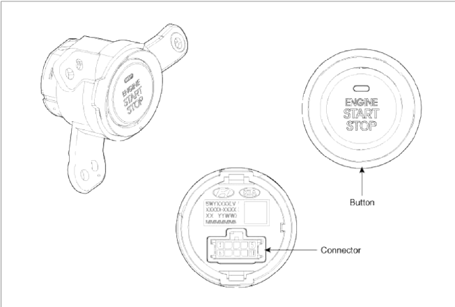
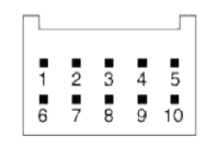
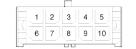 Connector (10 pins)
- Start stop button switch 1
- LED illumination power
- Amber LED
- Start stop button illumination GND
- Start stop button illumination Power
- Ground
- Start stop button switch 2
- Green LED
- Rheostat
- -
Repair procedures
Removal
1. Disconnect the negative(-) battery terminal.
2. Remove the cluster fascia panel. (Refer to the BD group - "Crash pad")
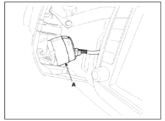
3. Disconnect the connector (A).
4. Remove the start/stop button (A) after loosening the mounting 3 screws.

Installation
1. Install the start/stop button.
2. Install the left aft vent.
Fob Holder
Components and Components Location
Component
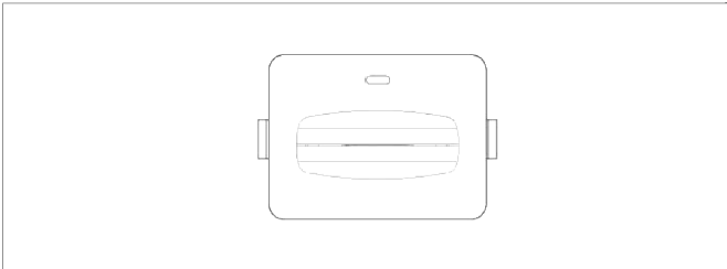
 Connector (10 pins)
- -
- Immobilizer dock
- Holder illumination
- GND
- GND
- Battery
- Immobilizer data
- Illumination battery
- Fob in
- -
Repair procedures
Removal
1. Disconnect the negative (-) battery terminal.
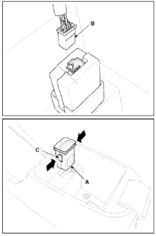
2. Remove the floor console. (Refer to the BD group - "Console")
3. Disconnect the connector (B), then remove the fob holder assembly (A) after releasing the hook (C).
Installation
1. Install the fob holder assembly.
2. Install the floor console.
3. Install the negative (-) battery terminal
READ NEXT:
 Ignition Switch Assembly
Repair procedures
Inspection
1. Disconnect the ignition switch connector (B) and key warning switch
connector (A) from under the steering column.
2. Check for continuity between the ter
Back View Camera System
Components and Components Location
Component Location
Back view camera
ECM mirror
Schematic Diagrams
Circuit Diagram
Back view camera connector
Power
Video (+)
Gr
SEE MORE:
Opening the hood
The hood serves as a cover for the
engine compartment.
Open the hood if maintenance work
needs to be performed in the engine
compartment or if you need to look at
the compartment.
Opening the hood
Pull the release lever to unlatch the
hood. The hood should pop open
slightly.
Manifold Absolute Pressure Sensor (MAPS)
Description
and Operation
Description
Manifold Absolute Pressure Sensor (MAPS) is a speed-density type sensor and
is installed on the surge tank. It
senses absolute pressure of the surge tank and transfers the analog signal
proportional to the pressure to the ECM.
By using this sign
Content
- Home
- Kia Sportage - Fifth generation (NQ5) - (2022-2026) - Owner's Manual
- Kia Sportage - Second generation (JEKM) (2005-2015) - Body Workshop Manual
- Kia Sportage Third generation (SL) - (2011-2016) - Service and Repair Manual
- Sitemap
- Top articles
