Kia Sportage: Components and Components Location
Components Location
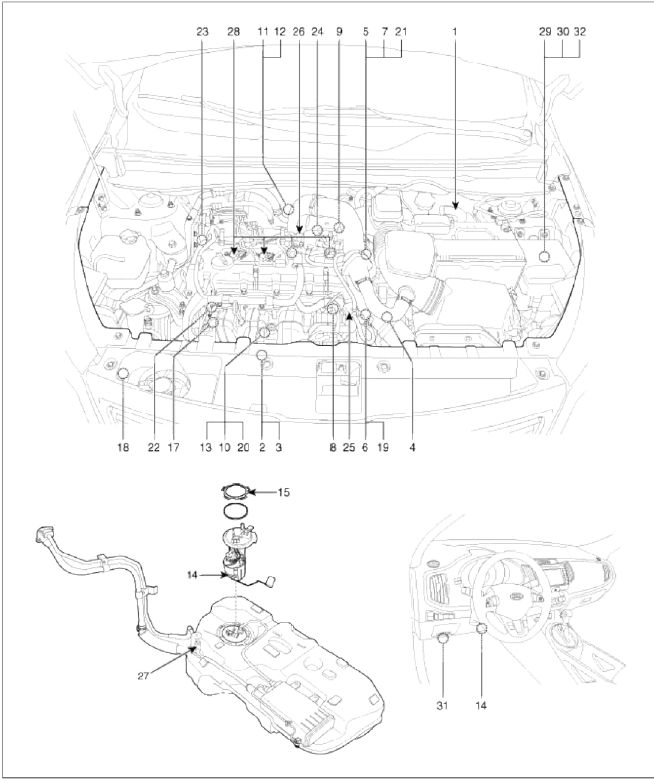
- Engine Control Module (ECM)
- Manifold Absolute Pressure Sensor (MAPS) #1
- Intake Air Temperature Sensor (IATS)
- Manifold Absolute Pressure Sensor (MAPS) #2
- Engine Coolant Temperature Sensor (ECTS)
- Throttle Position Sensor (TPS) [integrated into ETC Module]
- Crankshaft Position Sensor (CKPS)
- Camshaft Position Sensor (CMPS) [Bank 1 / Intake]
- Camshaft Position Sensor (CMPS) [Bank 1 / Exhaust]
- Knock Sensor (KS)
- Heated Oxygen Sensor (HO2S) [Bank 1 / Sensor 1]
- Heated Oxygen Sensor (HO2S) [Bank 1 / Sensor 2]
- Rail Pressure Sensor (RPS)
- Accelerator Position Sensor (APS)
- Fuel Tank Pressure Sensor (FTPS)
- Fuel Level Sensor (FLS)
- CVVT Oil Temperature Sensor (OTS)
- Ð/С Pressure Transducer (APT)
- ETC Motor [integrated into ETC Module]
- Injector
- Purge Control Solenoid Valve (PCSV)
- CVVT Oil Control Valve (OCV) [Bank 1 / Intake]
- CVVT Oil Control Valve (OCV) [Bank 1 / Exhaust]
- Electric Waste Gate Actuator (EWGA)
- RCV Control Solenoid Valve
- Fuel Pressure Regulator Valve
- Canister Close Valve (CCV)
- Ignition Coil
- Main Relay
- Fuel Pump Relay
- Data Link Connector (DLC) [16-Prn]
- Multi-Purpose Check Connector [20-Pm]
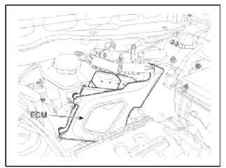
1. Engine Control Module (ECM)
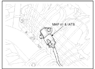
2. Manifold Absolute Pressure Sensor (MAPS) #1
3. Intake Air Temperature Sensor (IATS)
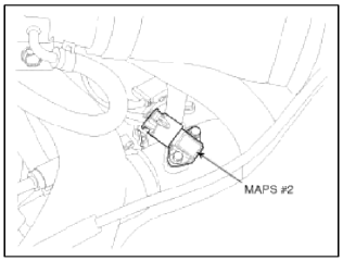
4. Manifold Absolute Pressure Sensor (MAPS) #
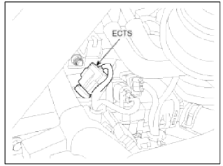
5. Engine Coolant Temperature Sensor (ECTS)
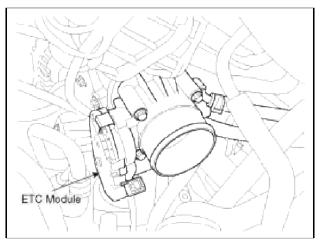
6. Throttle Position Sensor (TPS)
19. ETC Motor
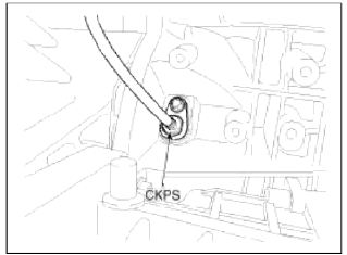
7. Crankshaft Position Sensor (CKPS)
![8. Camshaft Position Sensor (CKPS) [Bank 1 / Intake]](images/books/1921/21/index%2051.png)
8. Camshaft Position Sensor (CKPS) [Bank 1 / Intake]
![9. Camshaft Position Sensor (CKPS) [Bank 1 / Exhaust]](images/books/1921/21/index%2052.png)
9. Camshaft Position Sensor (CKPS) [Bank 1 / Exhaust]
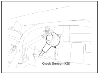
10. Knock Sensor (KS)
![11. Heater Oxygen Sensor (HO2S) [Bank 1 / Sensor 1]](images/books/1921/21/index%2054.png)
11. Heater Oxygen Sensor (HO2S) [Bank 1 / Sensor 1]
![12. Heater Oxygen Sensor (HO2S) [Bank 1 / Sensor 2]](images/books/1921/21/index%2055.png)
12. Heater Oxygen Sensor (HO2S) [Bank 1 / Sensor 2]
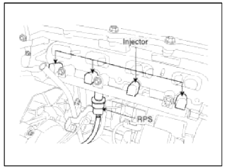
13. Rail Pressure Sensor (RPS)
20. Injector
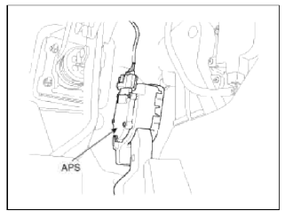
14. Accelerator Position Sensor (APS)
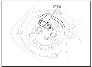
15. Fuel Pressure Sensor (FTPS)
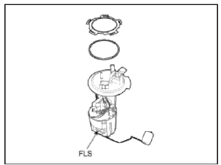
16. Fuel Level Sensor (FLS)
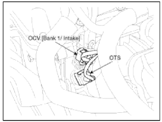
17. CVVT Oil Temperature Sensor (OTS)
22. CVVT Oil Control Valve (OCV) [Bank 1 / Intake
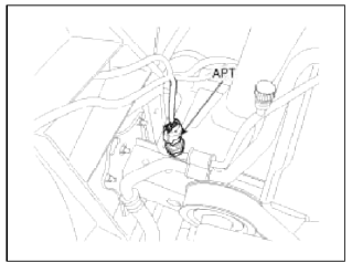
18. Ð/С Pressure Transducer (APT)
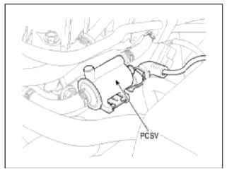
21. Purge Control Solenoid Valve (PCSV)
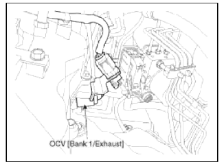
23. CVVT Oil Control Valve (OCV) [Bank 1 / Exhaust]
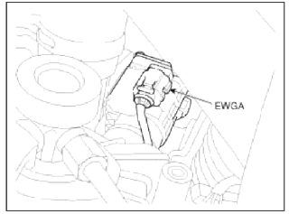
24. Electric Waste Gate Actuator (EWGA)
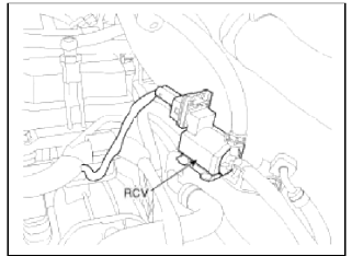
25. RCV Control Solenoid Valve
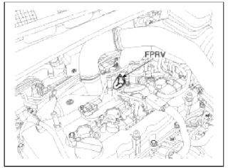
26. Fuel Pressure Regulator Valve
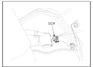
27. Canister Close Valve (CCV)
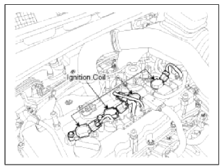
28. Ignition Coil
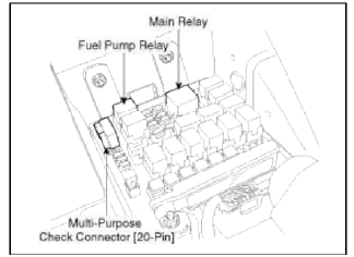
29. Main Relay
30. Fuel Pump Relay
32. Multi-Purpose Check Connector [20-Pin]
![31. Data Link Connector (DLC) [16-Pin]](images/books/1921/21/index%2070.png)
31. Data Link Connector (DLC) [16-Pin]
READ NEXT:
 Engine Control Module (ECM)
Schematic Diagrams
ECM Terminal And Input/Output signal
ECM Terminal Function
Connector [CHTG-AG]
Connector [CHTG-BG]
ECM Terminal Input/Output signal
Connector [CHTG-AG]
ETC (Electronic Throttle Control) System
Description and
Operation
Description
The Electronic Throttle Control (ETC) System consists of a throttle body with
an integrated control motor and
throttle position sensor (TPS). Instead
Manifold Absolute Pressure Sensor (MAPS)
Description
and Operation
Description
Manifold Absolute Pressure Sensor (MAPS) is a speed-density type sensor and
is installed on the surge tank. It
senses absolute pressure of the surge t
SEE MORE:
Front Washer Motor
Repair procedures
Inspection
Front Washer Motor
1. With the washer motor connected to the reservoir tank, fill the reservoir
tank with washer fluid.
NOTE
Before filling the reservoir tank with water, check the filter for foreign
material or contamination. If
necessary, clean the filt
Highway Driving Assist operation
Display and control
You can see the status of the Highway
Driving Assist operation in the Driving
Assist view on the cluster. Refer to
"Instrument cluster"
Highway Driving Assist will be displayed
as below depending on the status of the
function.
Operating State
Standby St
Content
- Home
- Kia Sportage - Fifth generation (NQ5) - (2022-2026) - Owner's Manual
- Kia Sportage - Second generation (JEKM) (2005-2015) - Body Workshop Manual
- Kia Sportage Third generation (SL) - (2011-2016) - Service and Repair Manual
- Sitemap
- Top articles
