Kia Sportage: Underdrive Brake Control Solenoid Valve (UD/B_VFS) | Overdrive Clutch Control Solenoid Valve (OD/C_VFS)
Description and Operation
Description
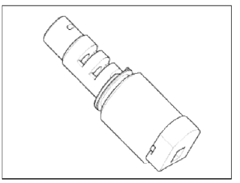
Underdrive brake control solenoid valve (UD/B_VFS) is attached to the valve body. This variable force solenoid valve directly controls the hydraulic pressure inside the underdrive brake.
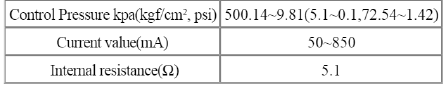
Specifications
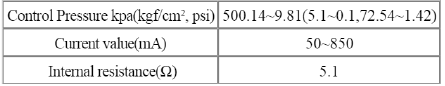
Specifications
Direct control VFS [35R/C]
Control type : Normal low type
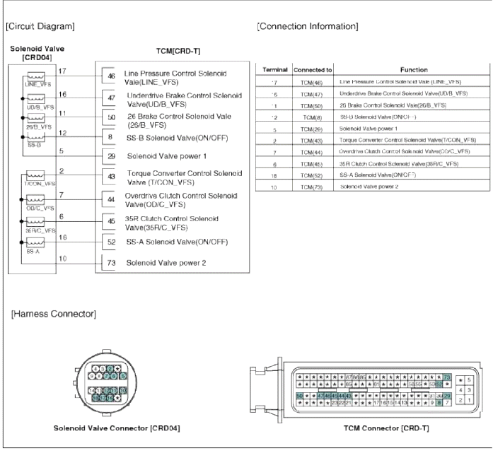
Schematic Diagrams
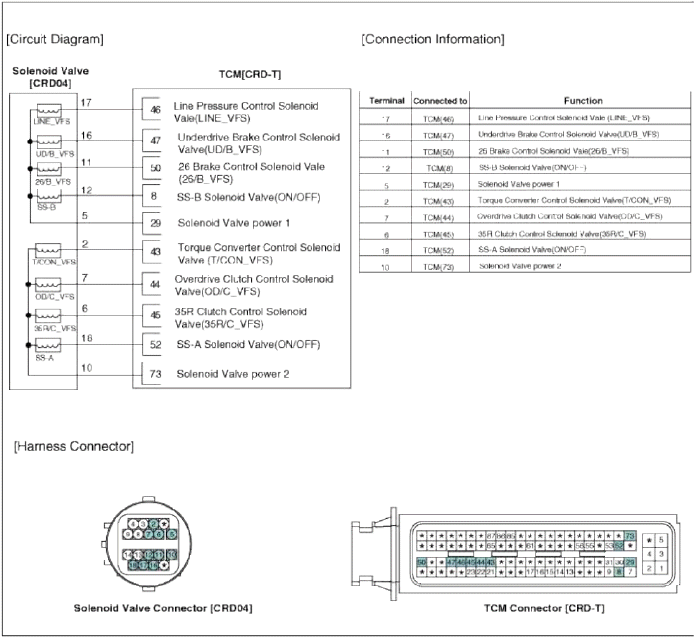
Circuit Diagram
Repair procedures
Inspection
1. Turn ignition switch OFF.
2. Disconnect the oil temperature sensor connector.
3. Measure resistance between sensor signal terminal and sensor ground terminal.
4. Check that the resistance is within the specification.
Removal
NOTE
Replacing an on/off solenoid valve (SS-A, SS-B) does not require additional hydraulic pressure adjustment; however, the hydraulic pressure will need to be adjusted after replacing the VFS solenoid valve. If replacing the VFS solenoid valve; also replace the valve body assembly. (Refer to "Valve Body" in this group)
Overdrive Clutch Control Solenoid Valve (OD/C_VFS)
Description and Operation
Description
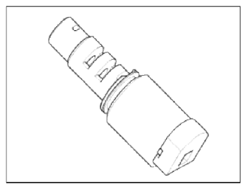
Overdrive clutch control solenoid valve (OD/C_VFS) is attached to the valve body. This variable force solenoid valve directly controls the hydraulic pressure inside the overdrive clutch.
Specifications
Specifications
Direct control VFS [35R/C]
Control type : Normal low type
Schematic Diagrams
Circuit Diagram
Repair procedures
Inspection
1. Turn ignition switch OFF.
2. Disconnect the oil temperature sensor connector.
3. Measure resistance between sensor signal terminal and sensor ground terminal.
4. Check that the resistance is within the specification
Removal
NOTE
Replacing an on/off solenoid valve (SS-A, SS-B) does not require additional hydraulic pressure adjustment; however, the hydraulic pressure will need to be adjusted after replacing the VFS solenoid valve. If replacing the VFS solenoid valve; also replace the valve body assembly. (Refer to "Valve Body" in this group)
READ NEXT:
 SS-A Solenoid Valve (ON/OFF)
Description and Operation
Description
SS-A solenoid valve is attached to the valve body and is an on/off solenoid
valve that is used to change gears. SS-A
Solenoid valve (ON/OFF) is install
SS-B Solenoid Valve (ON/OFF)
Description and Operation
Description
SS-B solenoid valve is attached to the valve body and is an on/off solenoid
valve that is used to change gears. SS-B
Solenoid valve (ON/OFF) is install
SEE MORE:
Exterior features
Roof rack
If the vehicle has a roof rack, you can
load cargo on top of your vehicle.
Type A
Type B
* The actual shape may differ from the
illustration.
Crossbars and fixing components
needed to install the roof rack on your
vehicle may be obtained from an authorized
Kia dealer or other
Hazardous driving conditions
If driving conditions deteriorate due to
poor weather or road conditions, you
should pay even more attention than
usual to your driving.
Hazardous driving conditions
When hazardous driving conditions are
encountered such as water, snow, ice,
mud, sand, or similar hazards, follow
these sugges
Content
- Home
- Kia Sportage - Fifth generation (NQ5) - (2022-2025) - Owner's Manual
- Kia Sportage - Second generation (JEKM) (2005-2015) - Body Workshop Manual
- Kia Sportage Third generation (SL) - (2011-2016) - Service and Repair Manual
- Sitemap
- Top articles
