Kia Sportage: SS-B Solenoid Valve (ON/OFF)
Description and Operation
Description
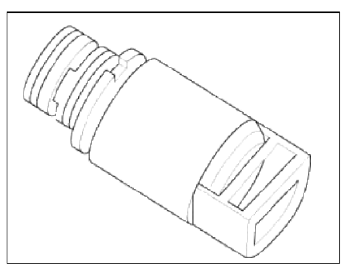
SS-B solenoid valve is attached to the valve body and is an on/off solenoid valve that is used to change gears. SS-B Solenoid valve (ON/OFF) is installed at valve body.
Specifications
Specifications
ON/OFF Solenoid Valve (SS-A, SS-B)
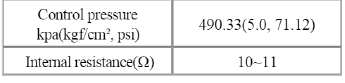
Control type : Normal low type
Schematic Diagrams
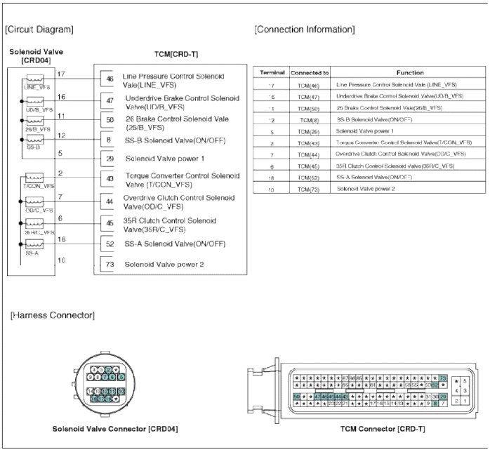
Circuit Diagram
Repair procedures
Inspection
1. Turn ignition switch OFF.
2. Disconnect the oil temperature sensor connector.
3. Measure resistance between sensor signal terminal and sensor ground terminal.
4. Check that the resistance is within the specification.
Removal
NOTE
Replacing an on/off solenoid valve (SS-A, SS-B) does not requite additional hydraulic pressure adjustment; however, the hydraulic pressure will need to be adjusted after replacing the VFS solenoid valve. If replacing the VFS solenoid valve; also replace the valve body assembly. (Refer to "Valve Body" in this group)
1. Remove the battery and the battery tray. (Refer to "Charging system" in EE group.)
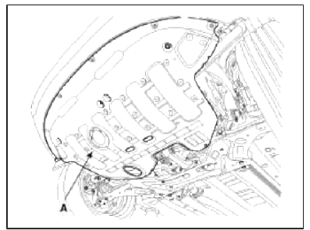
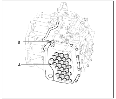
2. Remove the under cover (A).
Tightening torque: 19.6 ~ 24.5 N.m (2.0 ~ 2.5 kgf.m, 14.5 ~ 18.1 lb-ft)
3. Replace new gasket and the plug after draining the automatic transaxle fluid by removing the drain plug. (Refer to "Hydraulic system (Fluid)" in this group)
4. Remove the valve body cover (A) and eyebolt (B).
Tightening torque:
(A) 13.8 ~ 14.7 N.m (1.3 ~ 1.5 kgf.m, 9.4 ~ 10.8 lb-ft)
(B) 34.3 ~ 44.1 N.m (3.5 ~ 4.5 kgf.m, 25.3 ~ 32.6 lb-ft)
CAUTION
Always replace the gasket of the eyebolt use new one whenever loosening eyebolt.
NOTE
Remove installation bolts in the engin room first and then remove others under the vehicle.
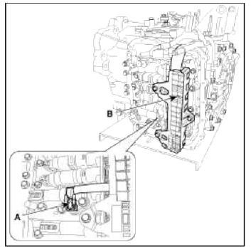
5. Remove the bolt (3ea) after disconnecting the solenoid valve connector (B) and the oil temperature sensor connector (A).
Tightening torque: 9.8 ~ 11.8 N.m (1.0 ~ 1.2 kgf.m, 7.2 ~ 8.7 lb-ft)
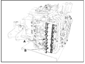
6. Remove the solenoid valve (B) after removing the solenoid support (A).
Installation
1. Installation is the reverse of removal.
NOTE
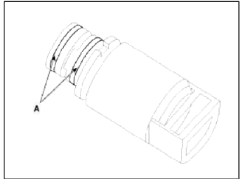
- When installing, apply the ATF oil or white vaseline to the O-ring (A) not to be damaged.
- Continue to apply liquid gasket at application points at the valve body cover with Ø2.5mm (0.0984in.) thickness.
Liquid gasket Part name : Threebond 1281B or LOCTITE FMD-546
- Adding automatic transaxle fluid. (Refer to "Hydraulic system (Fluid)" in this group)
READ NEXT:
 Inhibitor Switch
Description and Operation
Description
Inhibitor Switch monitors the lever's position (PRXD) and is used to control
gear setting signals.
Specifications
Specifications
Type: Co
Shift Lever
Components and Components Location
Components
Shift lever knob & boots
assembly
Shift lever assembly
Control cable assembly
Manual control lever (T/M side)
Repair procedure
SEE MORE:
Components and ComponentsLocation | Repair procedures
Component location
Coupling
Sub frame
Assist arm
Lower arm
Upper arm
Trailing arm
Coil spring
Shock absorber
Stabilizer
Drive shaft
Differential carrier assembly
Components
Lock nut
Tone wheel
Ð’J as
Adjustment - Repair procedures
Adjustment
Parking Brake Shoe Clearance Adjustment [2WD]
1. Raise the vehicle, and make sure it is securely supported.
2. Remove the rear tire and wheel.
3. Remove the plug from the disc.
4. Rotate the toothed wheel of adjuster by a screw driver until the disc is not
moving, and then retu
Content
- Home
- Kia Sportage - Fifth generation (NQ5) - (2022-2026) - Owner's Manual
- Kia Sportage - Second generation (JEKM) (2005-2015) - Body Workshop Manual
- Kia Sportage Third generation (SL) - (2011-2016) - Service and Repair Manual
- Sitemap
- Top articles
