Kia Sportage: Warning Control
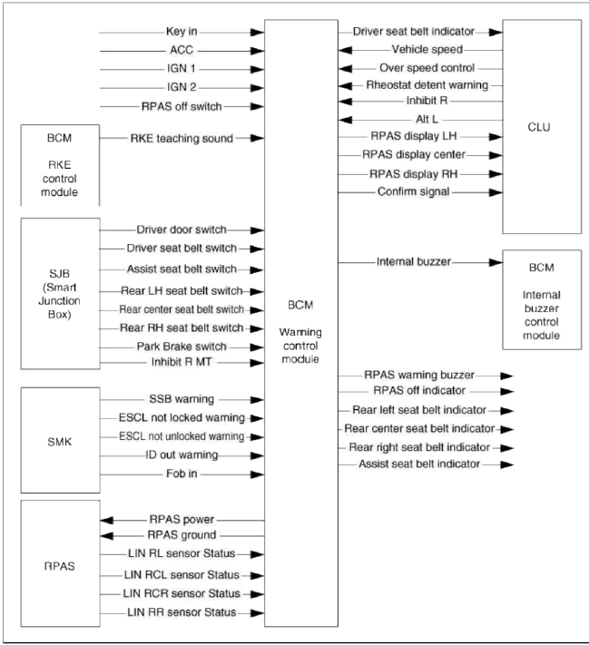

Warning Control
1. The Warning function offers the following features
- Seat Belt Warning
- Seat Belt Re minder
- Over Speed Warning
- Key Reminder Warning
- Parking Brake Warning
- RKE Key Teaching sound
- SMK System Warning
- RAPS Warning
- Rheostat Detent Warning
2. Buzzer Operation
- For Warning Sound Control Function, two types of Buzzers are used. One is Internal Buzzer, and it is located in BCM. The other is External Buzzer, and it is located in SMK.
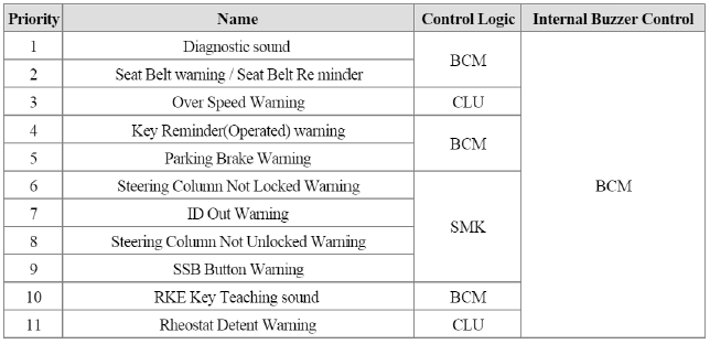
3. Priority of Warning Buzzer Condition
- If there are multiple warning conditions simultaneously, the warning shall activate the warning based on the pre-defined priority: (1st is the highest priority)
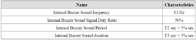
Internal Buzzer Sound Description
- BCM has an Internal Buzzer and Cluster has a Warning Indicator.
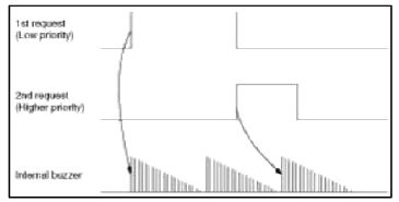
1. New request while buzzer activate by a previous request.
2. If a buzzer is active by a previous request, new request with higher priority cannot interrupt previous request. The new request will activate the buzzer as soon as the previous request sound period is completed.
3. Synchronization of Internal Warning Buzzer Sound and Indicator. To synchronize Indicator and Internal Warning buzzer. BCM sends the Indicator Blinking and activate Internal Warning Buzzer. Cluster checks received request and operates indicator.
Seat Belt Warning
1. When driver or passengers have their seat belts unfasten during driving, sound or indicator warning re mind them of fastening their seat belts.
2. Tins function offers following features
- Turn on/off and blinking Driver side seatbelt indicator depending on Driver side seatbelt switch input.
- Turn on/off and blinking Assistant side seatbelt indicator depending on Assistant side seatbelt switch input.
- Turn on/off Internal Warning Buzzer depending on Driver side or Assistant side seatbelt switch input.
- If vehicle speed exceeds a specific value, seatbelt indicator and Internal Warning Buzzer should be activated nr accordance with defined pattern.
3. General Description
- When driver unfasten his seat belts during driving, BCM warns driver by warning sound or indicator.
- Turn on/off and blinking Driver side seatbelt indicator depending on Driver side seatbelt switch input.
- Turn on/off Internal Buzzer depending on Driver side seatbelt switch input.
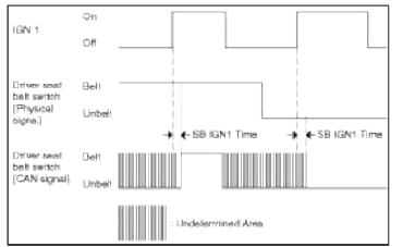
- Just after IGN1 On (A_IGNl = On), to get the Seat Belt
fastened/unfastened information, it takes about
"SBIGN1 Time (Typically 100 msec)", and before this time, J/Box indicates
that seatbelt is fastened via CAN.
So, from the moment IGN1 is On (A_IGNl = ON) and after "SBIGN1 Time", the seat belt/unbelt logic can start.
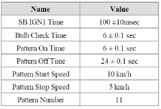
4. Seat Belt Reminder Function Description.
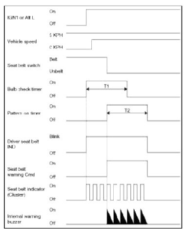
T1 : Bulb check time, T2 : Pattern on time
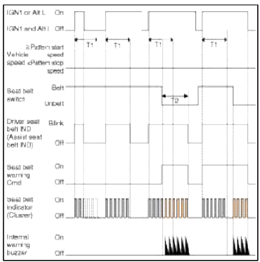
T1 : Bulb check time, T2 : Pattern on time
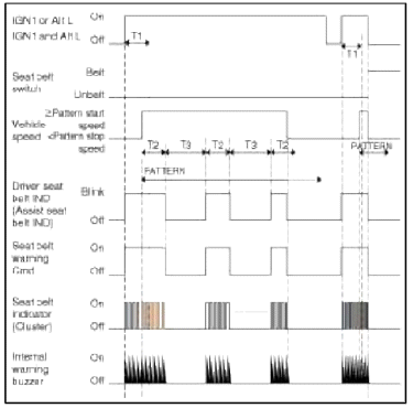
Т1 : Bulb check time, T2 : Pattern on time, T3 : Pattern off time
PATTERN : Pattern number tunes (T2 ON / T3 OFF)
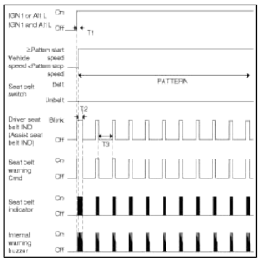
Т1 : Bulb check time, T2 : Pattern on time, T3 : Pattern off time
PATTERN : Pattern number tunes (T2 ON / T3 OFF)
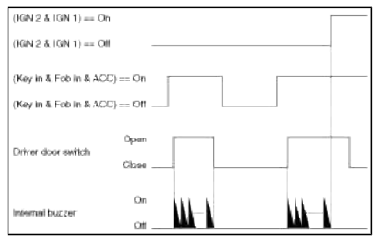
Key Reminder Warning (Key Operated Warning) Function
1. Internal Buzzer Control by Key Reminder Warning function.
2. If driver opens the driver side door and go away from the car during key is inserted or ACC state, a sound warning re minds a driver that key has to be taken off or ACC state has to be changed to Off state.
3. This warning Function does not operate in China Variant.
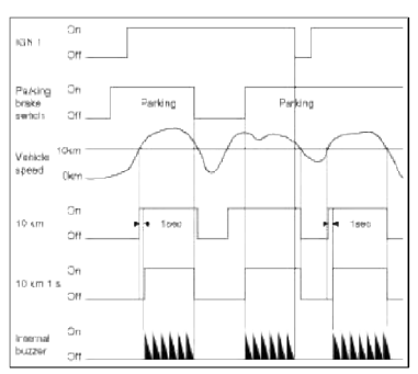
Parking Brake Warning
1. Internal Buzzer Control by Parking Brake Warning Function.
2. If driver drives the vehicle with parking brake On or not completely released and vehicle speed exceeds the specific value of l0km/h, a sound warning re minds the driver that parking brake has to be released.
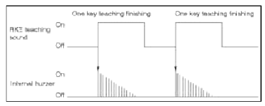
RKE Teaching Sound
1. Internal Buzzer Control by RKE Teaching Sound Function.
2. When each RKE's Teaching is ended, Warning buzzer is operated, one time.
SMK System Warning Sound
1. Internal Buzzer control for SMK System warning.
2. SMK System Warnings conditions of activation are controlled by the SMK unit. When a condition is satisfied, SMK unit sends corresponding warning request to BCM and cluster by CAN.
3. BCM only operates the Internal Buzzer.
4. The internal buzzer is controlled by the BCM and Sound duration is controlled by SMK.
- Steering Column Not Locked Warning
- This warning requires activation of the Internal Buzzer during C_ESCL_Notlocked_Warning = On.
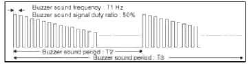
- SMK Warning Buzzer Sound Period : 0.6s + 0.06 sec
- ID Out Warning 1
- This warning requires activation of the Internal Buzzer during C_IDOUT_WNG = On.
- SMK Warning Buzzer Sound Period : 5s + 0.1 sec
- Steering Column Not Unlock Warning
- This warning requires activation of the Internal Buzzer during C_ESCL_Notunlocked_Warning = On.
- SMK Warning Buzzer Sound Period : 1s + 0.1 sec
- SSB Button Warning
- This warning requires activation of the Internal Buzzer during C_SSB_Warning = On.
- SMK Warning Buzzer Sound Period : 0.6s + 0.06 sec
Rheostat Detent Warning Sound
1. Internal Buzzer control for Rheostat Detent warning.
2. Rheostat Detent System Warnings conditions of activation are controlled by the CLU unit. When a condition is satisfied, CLU unit sends corresponding warning request to BCM by CAN.
3. BCM only operates the Internal Buzzer.
4. The internal buzzer is controlled by the BCM and Sound duration is controlled by BCM.
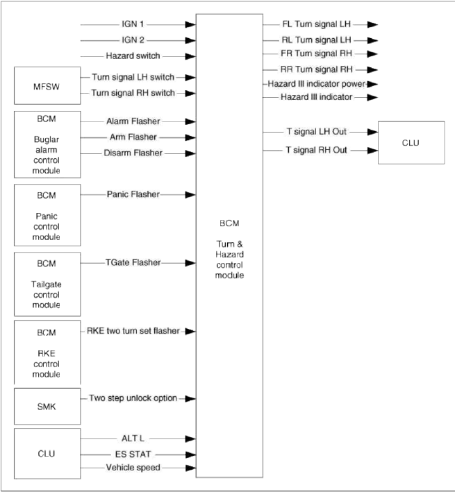
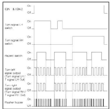
Turn and Hazard Control
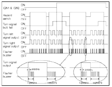
Flasher Buzzer Control Function
1. To provide an audible feedback to the driver when flasher is active, a Flasher Buzzer is used.
2. While Flasher Lamp is operated, the flasher buzzer is activated at the time of Output On Off transition.
3. Flasher Buzzer is controlled by the Cluster.
4. BCM turns on/off the turn left or/and turn Right flasher, cluster controls the flasher buzzer following the activation request from BCM.
![Т1 : 2 [KHz], 50% duty](images/books/1921/9/index%20222.png)
Т1 : 2 [KHz], 50% duty
Hazard Control Function
1. Activating the Hazard switch generates the Hazard signal, regardless of the Ignition key position. The Hazard signal is a permanent sequence. It goes off when the Hazard switch is deactivated. The signal drives both the Left and Right sides.
2. If it is detected the Bulb failure, flasher starts fault flashing. But it is only possible in IGN1 and IGN2 (A_IGN1 = On & L_IGN2 = On) on status.
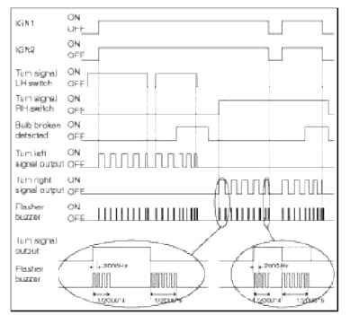
Turn Signal Control Function
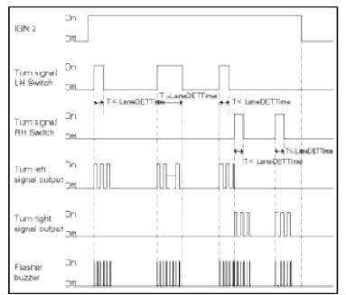
1. If the Left (or Right) turn switch is active and if IGN2 is On, the left (or Right) turn signal outputs are driven.
2. The turn signal is active as long as both conditions ((L_TurnSigLHSW or L_TurnSigRHSW = On) and L_IGN2 = On) are true and is turned Off when one of these conditions is no longer detected.
3. If bulb failure (outage or open load) is detected on the activated turn signal side, the flasher is operated with fault flashing.
4. This failure can be detected only when IGN1 and IGN2 On (A_IGN1 = On and L IGN2 = On).
5. While Turn switch is On and failure was detected, even if bulb failure is no longer detected, keep the fault flashing and after next Turn switch On or IGN On transition, flasher is activated with normal blinking.
Lane Change Turn Signal Control Function
1. Flasher lane-change feature means that a momentary activation of the turn switch will cause 3 flashes on the indicator circuit.
2. This lane-change feature operates under the following conditions:
- Lane change mode enabled (b_LaneEnable = On)
- Ignition 2 shall be On. and the lane change feature is not available if Ignition 2 is Off
- During flashing by lane change mode, it should detect the "Bulb-Failure" mode.
- During the Lane Change mode operation, if the user moves the turn switch to the other direction, then Lane change mode is finished and the other direction's flashing (Normal or Lane change flashing) will start depending on the Turn Switch On Period.
Flasher Failure Control Function
1. This function describes the following features
- Bulb Failure Detection
- SCG (SHORT to GND) Fault detection
2. BCM is monitoring the Turn Signal Output.
3. During Turn signal control or Hazard control, if Bulb failure detected, Flasher is operated with fault flashing.
4. Bulb Failure Detection Condition
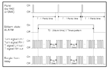
Burglar Alarm Flashing Control Function
1. This function describes the following features:
- Management of request for Alarm flashing by Burglar Alarm Manager
- Alarm Flashing Control
- Arm Flashing Control
- Disarm Flashing Control
2. Alarm Flashing Control
- If there is a request for having the alarm flashing (b_AlarmFlasher = On), a pattern of Turn left and turn right bulb flashing is performed.
- When the request is no longer present (b_AlarmFlasher = Off) the driving of the turn left and turn right bulbs flashing by Alarm is stopped without delay.
- The flashing shall be synchronized with Horn Alarm activation.
- Depending on the valiant setting, flashing pattern consist in 1 or 3 group of flashing as described in below figure.
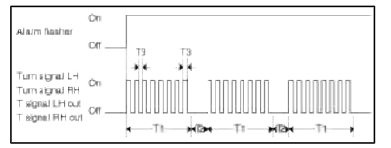
T1 : 27 sec + 0 sec / -2.7 sec, T2 : 10 sec +- 1 sec, T3 : 450 msec +- 45 msec
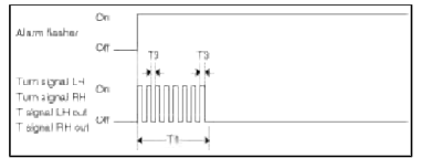
T1 : 27 sec + 0 sec / -2.7 sec, T3 : 450 msec +- 45 msec
3. Arm/Disarm Flashing Control
- If there is a request for having the arm flashing (b_ArmFlasher = Off → On) or disarm flashing (b_DisarmFlasher == Off → On), a pattern of Turn left and turn right bulb flashing is performed.
- Arm Flashing Pattern
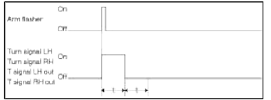
T : 1 sec +- 0.1 sec
- Disarm Flashing Pattern
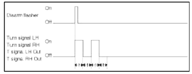
T : 500 msec +- 5 0 msec
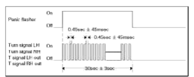
Panic Flashing Control Function
1. If there is a request for having the Panic flashing (b_PanicFlasher == On), a pattern of Turn left and turn right bulb flashing is performed.
2. When the request is no longer present (b_PanicFlasher = Off) the driving of the turn left and turn right bulbs flashing by Panic is stopped without delay.
3. The flashing shall be synchronized with Horn activation.
Tailgate Flashing Control Function
1. If there is a request for having the Tailgate flashing (b_TGateFlasher = Off →On). a pattern of Turn left and turn right bulb flashing is performed.
2. Tailgate flashing is two times flash ,each operation time is 500ms having 500ms pausing time.
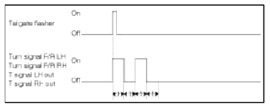
T : 500 msec = 50 msec
RKE Two Turn Unlock Set Flashing Control Function
1.This function describes the following features:
- Management of request for RKE Two Turn Unlock Set Reset complete flashing by RKE Lock Control Manager and SMK unit
2. Function Description
- If there is a request for having the Two Turn Unlock Set/Reset flashing by RKE (b_RKETwoTurnSetFlasher = Off→On) or by SMK RKE (C_TwoStepUnlockOption = Off→On), a pattern of Turn left and turn right bulb flashing is performed.
- RKE Two Turn Unlock Set/Reset flashing has four times flashing in 2s, each operation has 250ms ON time and 250ms OFF tune.
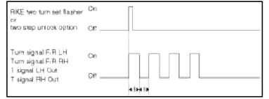
T : 250 msec +- 25 msec
Flasher Function Priority Control Function
1. If conditions of activating flashing conflict with each other, functional priorities are as following :
- Arm / Disarm Flashing (Burglar Alarm system)
- Burglar Alarm Flashing (Burglar Alarm system)
- Panic Flashing
- Hazard Flashing
- Turn Signal Flashing
- Tailgate Flashing
- RKE Two Turn Set/Reset Flasher
2. Turn Signal and Hazard Priority
- During Hazard flashing, if Turn Flashing is requested, keep the Hazard operation.
- During turn flashing, if Hazard flashing is requested, interrupt the turn flashing and start Hazard operation immediately.
- During Hazard operation if Hazard and Turn SW are On at the same time, if Hazard SW is turned Off turn flashing starts to operate but, does not discontinue the running period.
3. Burglar Alarm and Panic Priority
- Panic Alarm must be independent of the Burglar Alarm state (ARM, DISARM,
ALARM....) but is stopped
when entering in ARM mode.
- During Burglar Alarm is in progress, a panic alarm function can be started and stopped
- During Panic Alarm Flashing is in progress, a Burglar Alarm can start.
- The activation of the horn and hazard lamps by Burglar Alarm is higher priority than Panic mode
- If Alarm is in progress (3 Times pattern) during the 10s off time of the pattern the horn should be off.
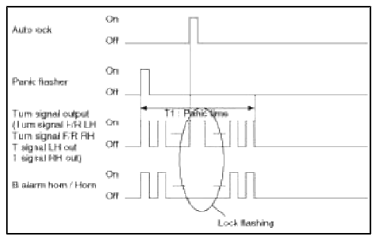
4. Autolock and Panic Priority
- During the activation of Horn and Hazard by Panic-Alarm, if get a AutoLock (b_AutoLockCmd) request from Burglar Alarm Function, it keeps the activation of Horn and Hazard by Panic-Alarm but do lock flashing.
READ NEXT:
 Doors Lock/Unlock Control
Central Door Lock/Unlock Function
1. If the central locking/unlocking request is detected, central locking
function is operated and outputs all doors
lock/unlock during LockOutTime/UnlockO
Power Window Control | Key Interlock Solenoid Control
Power Window Timer Control
1. After IGN1 is On. Power Window can operate and after IGN1 Off it is possible to operate the Power window, for "PwdwTime"(30 sec +-3 sec).
2. During count
SEE MORE:
Forward/Reverse Parking Distance Warning settings
Forward/Reverse Parking Distance
Warning (PDW) (if
equipped)
Forward/Reverse Parking Distance
Warning will help warn the driver if a
person, an animal or an object is
detected within a certain distance from
the ultrasonic sensors when the vehicle
is moving forward or in reverse.
Detecting s
Owner maintenance
The following lists are vehicle checks
and inspections that should be performed
by the owner or an authorized
Kia dealer at the frequencies indicated
to help ensure safe, dependable operation
of your vehicle.
Any adverse conditions should be
brought to the attention of your dealer
as soon
Content
- Home
- Kia Sportage - Fifth generation (NQ5) - (2022-2026) - Owner's Manual
- Kia Sportage - Second generation (JEKM) (2005-2015) - Body Workshop Manual
- Kia Sportage Third generation (SL) - (2011-2016) - Service and Repair Manual
- Sitemap
- Top articles
