Kia Sportage: Components and Components Location | Removal - Repair procedures
Components
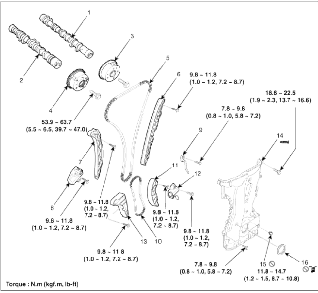
- Intake camshaft
- Exhaust camshaft
- Intake CVVT assembly
- Exhaust CVVT assembly
- Timing chain
- Timing chain guide
- Timing chain tensioner arm
- Timing chain tensioner
- Timing chain oil jet
- Balance shaft chain
- Balance shaft chain tensioner arm
- Balance shaft chain tensioner
- Balance shaft chain guide
- Timing chain cover
- Service hole bolt
- Crankshaft front oil seal
Removal - Repair procedures
Removal
CAUTION
- Use fender covers to avoid damaging painted surfaces.
- To avoid damage, unplug the wiring connectors carefully while holding the connector portion.
NOTE
Mark all wiring and hoses to avoid misconnection.
WARNING
In case of removing the high pressure fuel pump, high pressure fuel pipe, delivery pipe, and injector, there may be injury caused by leakage of the high pressure fuel. So don't do any repair work right after engine stops.
1. Remove the engine cover.
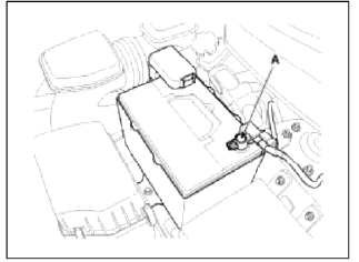
2. Disconnect the battery negative terminal (A).
3. Remove the air cleaner assembly.
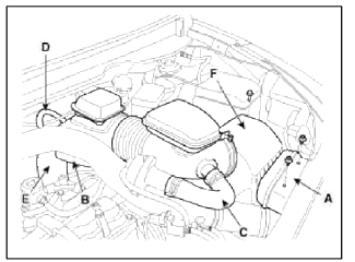
- Remove the air duct (A).
- Disconnect the breather hose (B), the recirculation hose (C) and the brake booster vacuum hose (D).
- Disconnect the air intake hose (E) and then remove the air cleaner assembly (F).
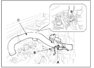
4. Disconnect the recirculation valve connector (A) and the vacuum hose (B), and then remove the intercooler inlet pipe & hose assembly (C).
5. Remove the RH front wheel.
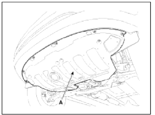
6. Remove the under cover (A).
7. Turn the crankshaft pulley and align its groove with the timing mark of the timing chain cover to set the piston of No. 1 cylinder to the top dead center on compression stroke.
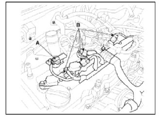
8. Disconnect the exhaust OCV (Oil control valve) connector (A) and the oxygen sensor connector (B).
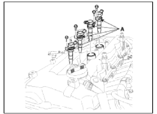
9. Disconnect the ignition coil connectors (B) and the fuel pump connector (A), then remove the wiring protector.
10. Remove the ignition coils (A).
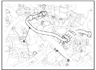
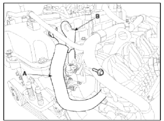
11. Disconnect the fuel hose (A) and PCSV (Purge control solenoid valve) hose (B).
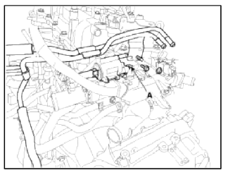
12. Disconnect PCSV (Purge control solenoid valve) connector (A) and loosen the vacuum pipe assembly mounting bolts and nut.
13. Remove the high pressure pipe (A). (Refer to FL group)
14. Remove the high pressure fuel pump (A) and the roller tappet (B). (Refer to FL group)
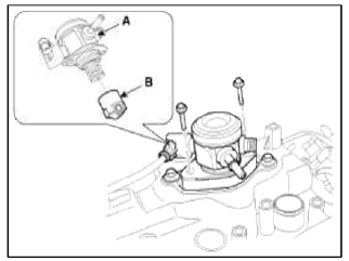
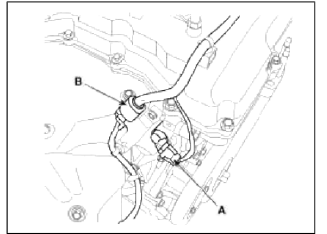
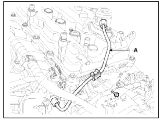
15. Disconnect the PCV (Positive crankcase ventilation) hose (A) and then remove the front engine hanger (B).
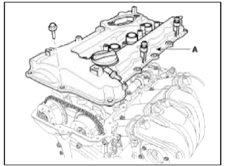
16. Remove the cylinder head cover (A).
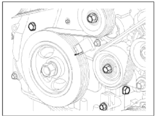
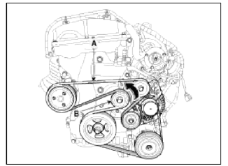
17. Remove the drive belt (A) after turning the drive belt tensioner (B) counterclockwise.
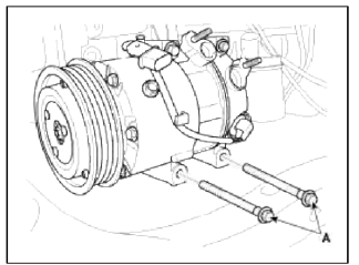
18. Remove the Ð/С compressor lower bolts (A).
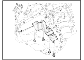
19. Remove the Ð/С compressor bracket (A).
20. Drain the engine oil.
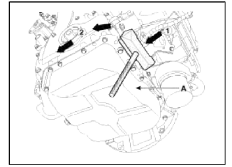
21. Remove the oil pan (A). Insert the blade of SST (09215-3C000) between the ladder frame and oil pan. Cut off applied sealer and remove the lower oil pan.
NOTE
- Insert the SST between the oil pan and the ladder frame by tapping it with a plastic hammer in the direction of (1) arrow.
- After tapping the SST with a plastic hammer along the direction of (2) arrow around more than 2/3 edge of the oil pan, remove it from the ladder frame.
- Do not turn over the SST abruptly without tapping. It is result in damage of the SST.
- Be careful not to damage the contact surfaces of ladder frame and lower oil pan.
22. Set the jack to the edge of ladder frame.
NOTE
Put the wooden block between ladder frame and jack.
CAUTION
Be careful not to damage the balance shaft & oil pump module.
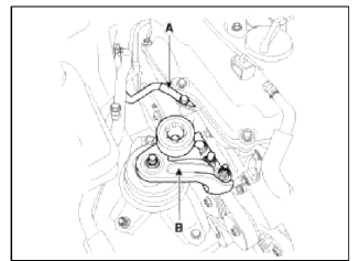
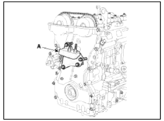
23. Disconnect the ground line (A), and then remove the engine mounting support bracket (B).
24. Remove the idler (A), the water pump pulley (B), the crankshaft pulley (C) and the drive belt tensioner pulley (D).
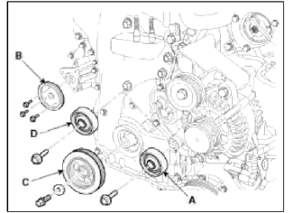
CAUTION
Tensioner pulley bolt is left-handed screw.
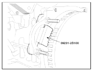
NOTE
Use the SST (Ring gear stopper, 09231-2B100) (A) to remove the crankshaft pulley bolt, after removing the starter.
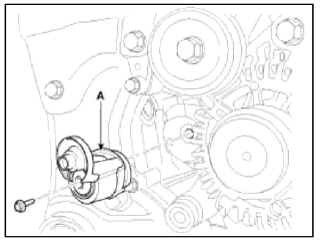
25. Remove the drive belt tensioner (A).
26. Remove the engine support bracket (A).
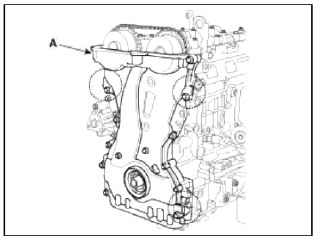
27. Remove the timing chain cover (A) by gently prying the portions between the cylinder head and cylinder block.
CAUTION
Be careful not to damage the contact surfaces of cylinder block, cylinder head and timing chain cover.
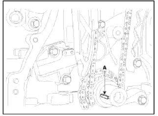
28. Make sure that the key (A) of crankshaft is aligned with the mating surface of main bearing cap. As a result of this, the piston of No.1 cylinder is placed at the top dead center on compression stroke.
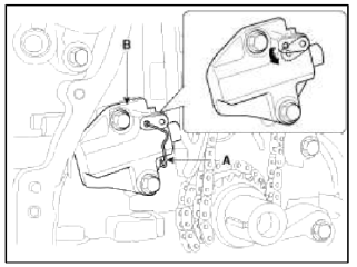
29. Release the ratchet by pulling the link down using a thin rod. Compress the piston and then insert a stopper pin (A) into the hole on the ratchet to hold the compressed piston. Remove the timing chain tensioner (B).
30. Remove the timing chain tensioner arm (A).
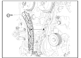
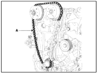
31. Remove the timing chain (A).
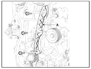
32. Remove the timing chain guide (A).
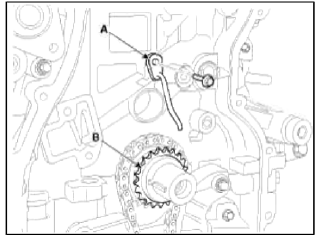
33. Remove the timing chain oil jet (A) and the crankshaft chain sprocket (B).
34. Remove the balance shaft chain. (Refer to Lubrication system in this group)
Inspection
Sprockets, Chain Tensioner, Chain Guide, Chain Tensioner Arm
1. Check the camshaft sprocket and crankshaft sprocket for abnormal wear, cracks, or damage. Replace as necessary.
2. Inspect the tensioner arm and chain guide for abnormal wear, cracks, or damage. Replace as necessary.
3. Check that the tensioner piston moves smoothly when the ratchet pawl is released with thin rod.
Drive belt, Idler, Pulley
1. Check the idler for excessive oil leakage, abnormal rotation or vibration. Replace if necessary.
2. Check belt for maintenance and abnormal wear of V-ribbed part. Replace if necessary.
3. Check the pulleys for vibration in rotation, oil or dust deposit of V-ribbed part. Replace if necessary.
READ NEXT:
 Installation - Repair procedures
Installation
1. Install the balance shaft chain. (Refer to Lubrication system in this
group)
2. Install the crankshaft chain sprocket (B) and the timing chain oil jet
(A).
Tightening torque:
7
SEE MORE:
General Safety Information and Caution
Precautions
General Precautions
Please read the following precautions carefully before performing the airbag
system service.
Observe the instructions described in this manual, or the airbags could
accidentally deploy and cause damage or
injuries.
Except when performing electrical i
Surround View Monitor operation
Parking/View button
Press the Parking/View button (1) to turn
on or off Surround View Monitor.
Front view
Front view function is displayed on the
screen when the gear is in N (Neutral) or
D (Drive) to assist in parking. The front
view has a top view, front view, side view
and 3D view.
Content
- Home
- Kia Sportage - Fifth generation (NQ5) - (2022-2026) - Owner's Manual
- Kia Sportage - Second generation (JEKM) (2005-2015) - Body Workshop Manual
- Kia Sportage Third generation (SL) - (2011-2016) - Service and Repair Manual
- Sitemap
- Top articles
