Kia Sportage: Components and Components Location | Repair procedures
Components Location
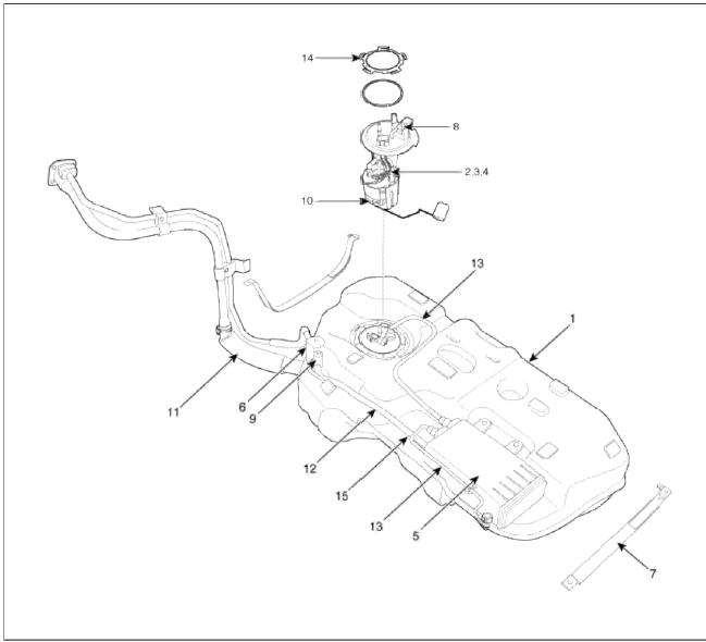
- Fuel tank
- Fuel pump
- Fuel filter
- Fuel pressure regulator
- Canister
- Fuel tank air filter
- Fuel tank band
- Fuel tank pressure sensor (FTPS)
- Canister close valve (CCV)
- Fuel level sensor (FLS)
- Fuel filler hose
- Ventilation hose
- Vapor tube
- Fuel pump locking ring
[High Pressure Fuel Line]
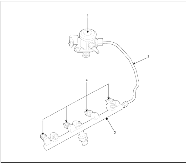
- High Pressure Fuel Pump
- High Pressure Fuel Pipe
- Delivery Pipe
- Injector
WARNING
In case of removing the high pressure fuel pump, high pressure fuel pipe, delivery pipe, and injector, there may be injury caused by leakage of the high pressure fuel. So don't do any repair work right after engine stops.
Repair procedures
Fuel Pressure Test
1. Release the residual pressure in fuel line (Refer to "Release Residual Pressure in Fuel Line" in this group).
CAUTION
When removing the fuel pump relay, a Diagnostic Trouble Code (DTC) may occur. Delete the code with the GDS after completion of "Release Residual Pressure in Fuel Line" work.
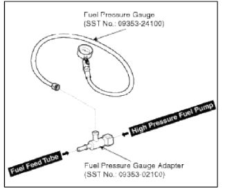
2. Install the Special Service Tool (SST).
- Disconnect the fuel feed tube from the high pressure fuel pump.
CAUTION
There may be some residual pressure even after "Release Residual Pressure in Fuel Line" work, so cover the hose connection with a shop towel to prevent residual fuel from spilling out before disconnecting any fuel connection.
- Install the special service tool for measuring the fuel pressure in between the fuel feed tube and the high pressure fuel pump (Refer to the figure below).
3. Inspect fuel leakage on connections among the fuel feed tube, the high pressure fuel pump, and the SST components with IG ON.
4. Measure Fuel Pressure
- Start the engine and measure the fuel pressure at idle.
Fuel Pressure: 493 ~ 507 kPa (5.0 ~ 5.2 kgf/cm2, 71.5 ~ 73.5 psi)
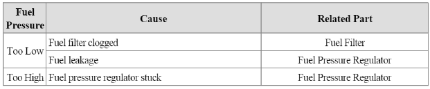
NOTE
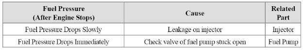
If the fuel pressure differs from the standard value, repair or replace the related part (Refer to the table below).
- Stop the engine, and then check for the change in the fuel pressure gauge reading.
Standard Value: The gauge reading should hold for about 5 minutes after the engine stops.
NOTE
If the gauge reading should not be held, repair or replace the related part (Refer to the table below).
- Turn the ignition switch OFF.
5. Release the residual pressure in fuel line (Refer to "Release Residual Pressure in Fuel Line").
CAUTION
When removing the fuel pump relay, a Diagnostic Trouble Code (DTC) may occur. Delete the code with the GDS after completion of "Release Residual Pressure in Fuel Line" work.
6. Test End
- Remove the Special Service Tool (SST) from the fuel feed tube and the high pressure fuel pump.
- Connect the fuel feed tube and the high pressure fuel pump.
Release Residual Pressure in Fuel Line
CAUTION
Whenever the high pressure fuel pump, fuel pipe, delivery pipe, or injector is removed immediately after shutting off the engine, an injury may be caused by the release of highly pressurized fuel. Release the residual pressure in the high pressure fuel line by referring to the "Residual fuel pressure release procedure" below before removing any high pressure fuel system components.
NOTE
Wear safety glasses and fuel resistant gloves.
1. Turn the ignition off and disconnect the battery negative cable.
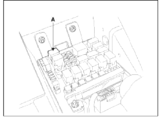
2. Remove the fuel pump relay (A).
3. Disconnect the electrical connector from the high pressure fuel pump.
4. Reconnect the battery negative cable.
5. Run the engine for about 20 seconds to lower the pressure in both the high or low pressure lines. The engine may shut off within the 20 second period. If not, turn the engine off.
6. Proceed with the service or repair. Use rags to cover opening and catch spills when opening up the high pressure system.
7. Reinstall / re-connect all components in reverse order of removal. Start engine and confirm proper operation, and make sure there are no fuel leaks.
8. After completing, clear DTC(s) using GDS scan tool (the procedure described above will cause DTC to set).
READ NEXT:
 Fuel Tank
Repair procedures
Removal
1. Release the residual pressure in fuel line (Refer to "Release Residual
Pressure in Fuel Line" in this group).
2. Remove the rear seat cushion (Refer to "Seat" in BD g
Fuel Pump
Repair procedures
Inspection
[Fuel pump]
1. Turn the ignition switch OFF, and then remove battery (-) cable.
2. Remove the fuel pump assembly.
3. Check motor operation by fuel pump conn
SEE MORE:
Brake fluid
Checking the brake fluid level
Check the fluid level in the reservoir
periodically. The fluid level should be
between MAX and MIN marks on the
side of the reservoir.
Before removing the reservoir cap
and adding brake fluid, clean the area
around the reservoir cap thoroughly
to prev
Blind-Spot Collision-Avoidance Assist operation
Blind-Spot Collision-Avoidance Assist
will warn and control as following operation.
Vehicle detection
Collision Warning
Collision-Avoidance Assist
Vehicle detection
Warning light will appear in the outside
rear view mirror when the vehicle on
both lanes is detected from the rear.
Content
- Home
- Kia Sportage - Fifth generation (NQ5) - (2022-2026) - Owner's Manual
- Kia Sportage - Second generation (JEKM) (2005-2015) - Body Workshop Manual
- Kia Sportage Third generation (SL) - (2011-2016) - Service and Repair Manual
- Sitemap
- Top articles
