Kia Sportage: Console
Components and Components Location
Components
[M/T]
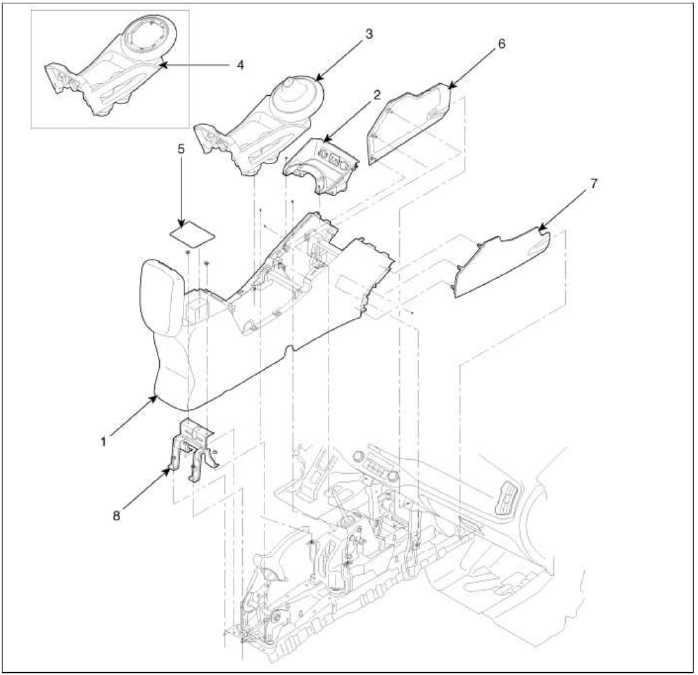
- Floor console assembly
- Floor console tray
- Console upper cover [5 speed M/T]
- Console upper cover [6 speed M/T]
- Console storage box mat
- Console side cover [LH]
- Console side cover [RH]
- Console rear mounting bracket
[Ð/T]
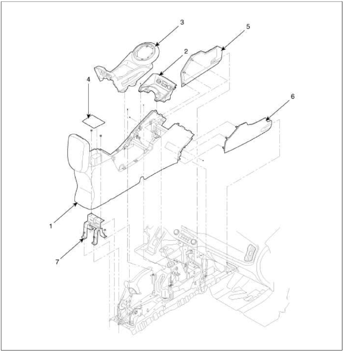
- Floor console assembly
- Floor console tray
- Console upper cover [A/T]
- Console storage box mat
- Console side cover [LH]
- Console side cover [RH]
- Console rear mounting bracket
Repair procedures
Replacement
Floor Console Replacement
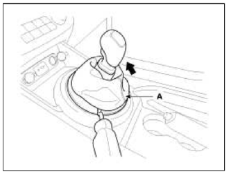
[M/T]
CAUTION
- When prying with a flat-tip screwdriver, wrap it with protective tape, and apply protective tape around the related parts, to prevent damage.
- Put on gloves to protect your hands.
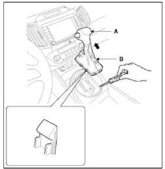
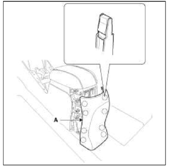
1. Using a screwdriver or remover, remove the gear boots (A).
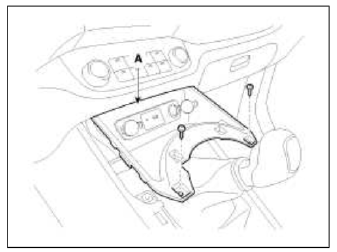
2. Using a screwdriver or remover, remove the console upper cover (A).
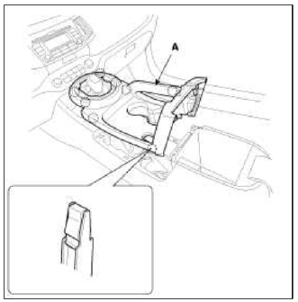
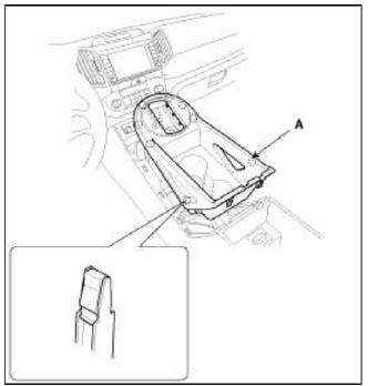
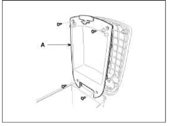
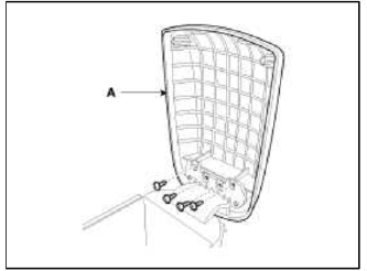
3. After loosening the mounting screws, then remove the floor console tray (A).
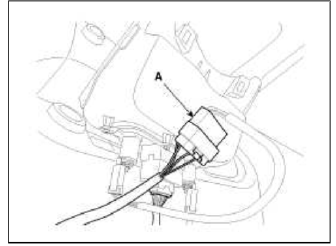
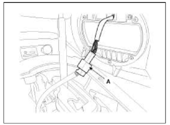
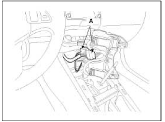
4. Disconnect the connector (A).
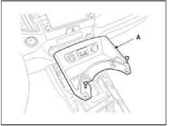
5. Remove the console side cover (A).
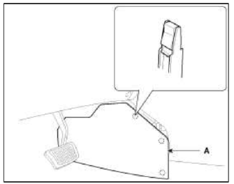
6. After loosening the mounting screws and bolts, then remove the floor console assembly (A).
7. Installation is the reverse of removal.
NOTE
- Make sure the connector are connected in properly.
- Replace any damage clips.
[Ð/T]
CAUTION
- When prying with a flat-tip screwdriver, wrap it with protective tape, and apply protective tape around the related parts, to prevent damage.
- Put on gloves to protect your hands.
1. Using a screwdriver or remover, remove the gear boots (B) and gear knob (A).
2. Using a screwdriver or remover, remove the console upper cover (A).
3. Disconnect the connector (A).
4. After loosening the mounting screws, then remove the floor console tray (A).
5. Disconnect the connector (A).
6. Remove the console side cover (A).
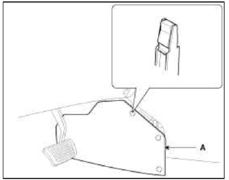
7. After loosening the mounting screws and bolts, then remove the floor console assembly (A).
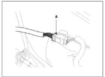
8. Disconnect the floor console main connector (A).
9. Installation is the reverse of removal.
NOTE
- Make sure the connector are connected in properly.
- Replace any damage clips.
Armrest Replacement
CAUTION
- When prying with a flat-tip screwdriver, wrap it with protective tape, and apply protective tape around the related parts, to prevent damage.
- Put on gloves to protect уоur hands.
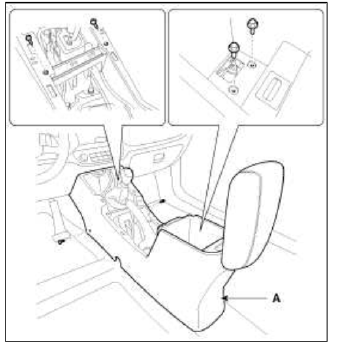
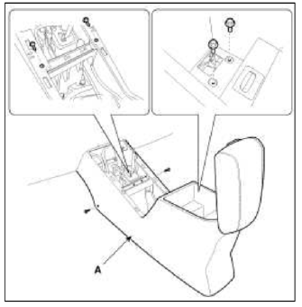
1. Using a screwdriver or remover, remove the rear console cover (A).
2. After loosening the mounting screws, then remove the armrest cover (A).
3. After loosening the mounting screws, then remove the armrest assembly (A).
4. Installation is the reverse of removal.
NOTE
- Replace any damage clips.
READ NEXT:
 Crash Pad
Components and Components Location
Components
Main crash pad assembly
Crash pad side cover
[LH]
Crash pad side cover
[RH]
Cluster fascia panel
Reinforcing panel
Crash pad lo
Roof Trim
Components and Components Location
Components
Roof trim
Sunvisor [Driver's]
Sunvisor [Passenger's]
Components [Panoramaroof]
Roof trim
Sunvisor [Driver's]
Interior Trim
Components and Components Location
Components
Front pillar trim
Center pillar upper trim
Center pillar lower trim
Luggage side trim
Cowl side trim
Front door scuff trim
Rear d
SEE MORE:
Closing the liftgate
To close the liftgate, lower and push
down the liftgate firmly. Make sure
that the liftgate is securely latched.
WARNING
Make sure your hands, feet and other
parts of your body are safely out of the
way before closing the liftgate.
WARNING
Exhaust fumes
The liftgate lid should be
Rear Stabilizer Bar | Rear Assist Arm
Repair procedures
Replacement
1. Remove the rear wheel & tire.
Tightening torque: 88.3 ~ 107.9N.m (9.0 ~ 11.0kgf.m, 65.1 ~ 79.6lb-ft)
CAUTION
Be careful not to damage to the hub bolts when removing the front wheel & tire (A).
2. Loosen the nut and then remove the rear stabiliz
Content
- Home
- Kia Sportage - Fifth generation (NQ5) - (2022-2026) - Owner's Manual
- Kia Sportage - Second generation (JEKM) (2005-2015) - Body Workshop Manual
- Kia Sportage Third generation (SL) - (2011-2016) - Service and Repair Manual
- Sitemap
- Top articles
