Kia Sportage: Crash Pad
Components and Components Location
Components

- Main crash pad assembly
- Crash pad side cover [LH]
- Crash pad side cover [RH]
- Cluster fascia panel
- Reinforcing panel
- Crash pad lower panel
- Center fascia panel
- Crash pad garnish
- Glove box housing
- Glove box
- Cowl cross bar assembly
Repair procedures
Replacement
Cluster Replacement
CAUTION
- When prying with a flat-tip screwdriver, wrap it with protective tape, and apply protective tape around the related parts, to prevent damage.
- Put on gloves to protect your hands.
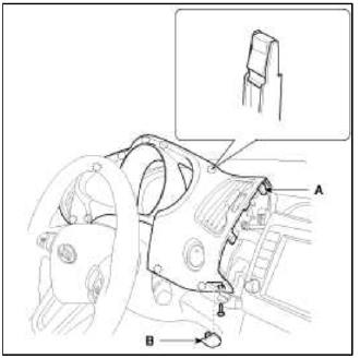
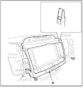
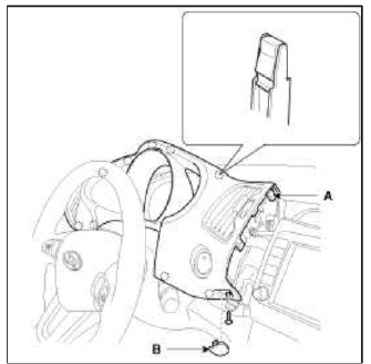
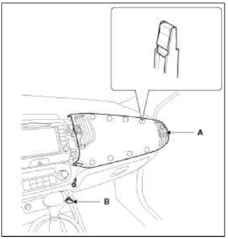
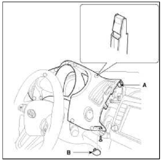
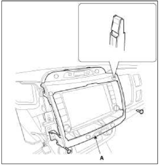
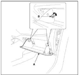
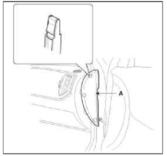
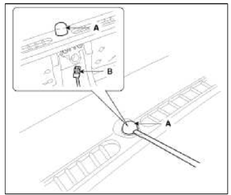
1. Remove the cluster fascia panel cap (B) and then loosening the mounting screw.
2. Using a screwdriver or remover, remove the cluster fascia panel (A).
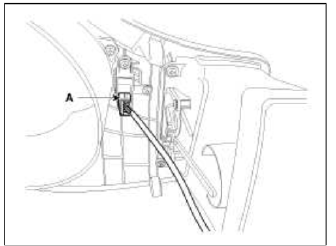
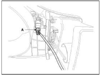
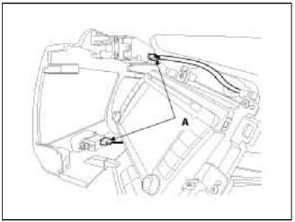
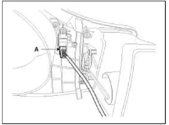
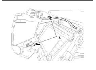
3. Disconnect the connector (A).
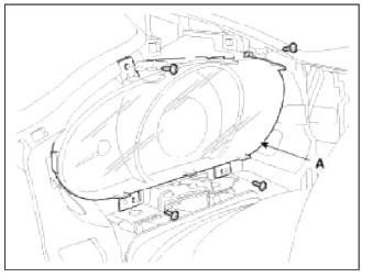
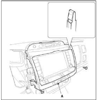
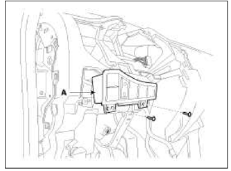
4. After loosening the mounting screws, then remove the cluster assembly (A).
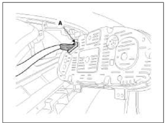
5. Disconnect the connector (A).
6. Installation is the reverse of removal.
NOTE
- Make sure the connector is plugged in properly.
- Replace any damage clips.
Center Fascia Panel Replacement
CAUTION
- When prying with a flat-tip screwdriver, wrap it with protective tape, and apply protective tape around the related parts, to prevent damage.
- Put on gloves to protect your hands.
1. Remove the cluster fascia panel cap (B) and then loosening the mounting screw.
2. Using a screwdriver or remover, remove the cluster fascia panel (A).

3. Disconnect the connector (A).
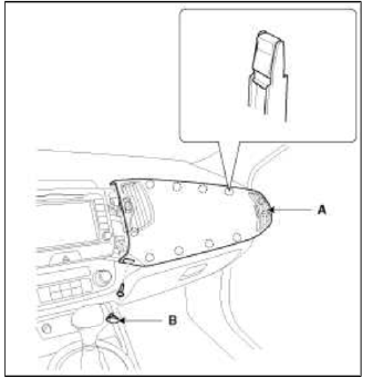
4. Remove the crash pad garnish cap (B) and then loosening the mounting screw.
5. Using a screwdriver or remover, remove the crash pad garnish (A).

6. After loosening the mounting screws, then remove the center fascia panel (A).
7. Disconnect the connectors (A).
8. Installation is the reverse of removal.
NOTE
- Make sure the connector are connected in properly.
- Replace any damage clips.
Crash Pad Lower Panel Replacement
CAUTION
- When prying with a flat-tip screwdriver, wrap it with protective tape, and apply protective tape around the related parts, to prevent damage.
- Put on gloves to protect your hands.
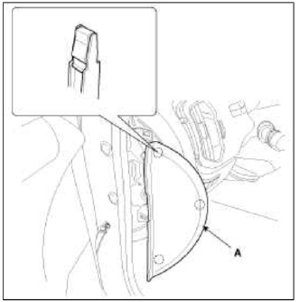
1. Using a screwdriver or remover, remove the crash pad side cover (A).
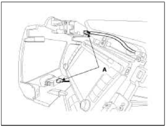
2. After loosening the mounting screws, then remove the crash pad lower panel (A).
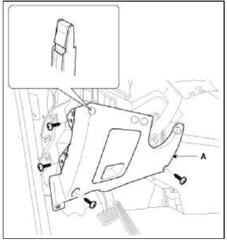
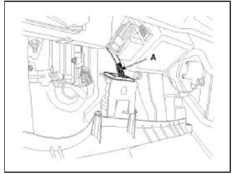
3. Disconnect the diagnosis connector (A).
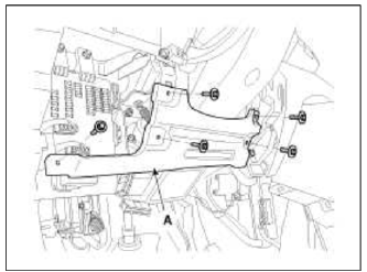
4. After loosening the mounting bolts, then remove reinforcing panel (A).
5. Installation is the reverse of removal.
NOTE
- Make sure the connector are connected in properly.
- Replace any damage clips.
Audio assembly Replacement
CAUTION
- When prying with a flat-tip screwdriver, wrap it with protective tape, and apply protective tape around the related parts, to prevent damage.
- Put on gloves to protect your hands.
1. Remove the cluster fascia panel cap (B) and then loosening the mounting screw.
2. Using a screwdriver or remover, remove the cluster fascia panel (A).
3. Disconnect the connector (A).

4. Remove the crash pad garnish cap (B) and then loosening the mounting screw.
5. Using a screwdriver or remover, remove the crash pad garnish (A).
6. After loosening the mounting screws, then remove the center fascia panel (A).
7. Disconnect the connectors (A).
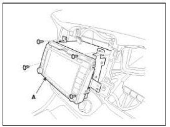
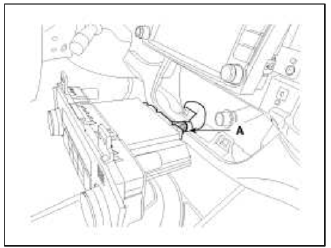
8. After loosening the mounting screws, then remove the audio assembly (A).
9. Disconnect the connectors (A).
10. Installation is the reverse of removal
NOTE
- Make sure the connector are connected in properly.
- Replace any damage clips.
Heater Control Unit Replacement
CAUTION
- When prying with a flat-tip screwdriver, wrap it with protective tape, and apply protective tape around the related parts, to prevent damage.
- Put on gloves to protect your hands.
1. Remove the cluster fascia panel cap (B) and then loosening the mounting screw.
2. Using a screwdriver or remover, remove the cluster fascia panel (A).
3. Disconnect the connector (A).
4. Remove the crash pad garnish cap (B) and then loosening the mounting screw.
5. Using a screwdriver or remover, remove the crash pad garnish (A).
6. After loosening the mounting screws, then remove the center fascia panel (A).
7. Disconnect the connectors (A).
8. After loosening the mounting screws, then remove the heater control unit (A).

9. Disconnect the connector (A).
10. Installation is the reverse of removal.
NOTE
- Make sure the connector are connected in properly.
- Replace any damage clips.
Glove Box Replacement
CAUTION
- When prying with a flat-tip screwdriver, wrap it with protective tape, and apply protective tape around the related parts, to prevent damage.
- Put on gloves to protect your hands.
1. Using a screwdriver or remover, remove the crash pad side cover (A).
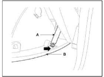
2. Disconnect the guide (B) from the glove box (A).
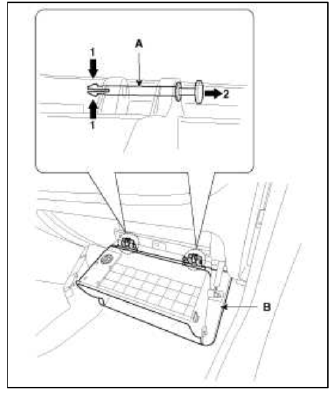
3. Disconnect the life (A) from the glove box (B).
4. Disconnect the pin (A) and then remove the glove box (B).
5. Installation is the reverse of removal.
NOTE
- Replace any damage clips.
Shroud Replacement
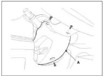
1. After loosening the mounting screws, then remove the shroud assembly (A).
2. Installation is the reverse of removal.
Crash Pad Side Cover Replacement
CAUTION
- When prying with a flat-tip screwdriver, wrap it with protective tape, and apply protective tape around the related parts, to prevent damage.
- Put on gloves to protect your hands.
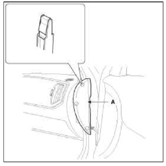
1. Using a screwdriver or remover, remove the crash pad side cover (A).
[Driver's]
![[Passenger's]](images/books/1921/5/index%20215.png)
[Passenger's]
2. Installation is the reverse the removal.
Main Crash Pad Replacement
CAUTION
- When prying with a flat-tip screwdriver, wrap it with protective tape, and apply protective tape around the related parts, to prevent damage.
- Put on gloves to protect your hands.
1. Remove the following items.
- Front seat (Refer to the BD group - "Front Seat")
- Front pillar trim (Refer to the BD group - "Interior Trim")
- Floor console assembly (Refer to the BD group - "Console")
- Cluster fascia panel & Cluster assembly
- Crash pad garnish
- Glove box
- Center fascia panel
- Audio assembly
- Heater control unit
- Crash pad side cover
- Cowl side trim (Refer to the BD group- Interior Trim")
- Crash pad lower panel
- Steering column (Refer to the ST group - "Steering Column and Shaft")
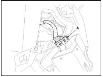
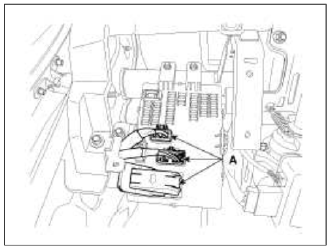
2. After loosening the mounting screws, then remove the crash pad switch assembly (A).
3. Disconnect the connector (A).
4. Disconnect the passenger's airbag connector (A).
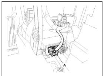
5. Loosen the mounting bolts.
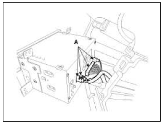
6. Using a screwdriver, remove the photo sensor (A).
7. Disconnect the photo sensor connector (B).
8. After loosening the mounting bolts and nuts, then remove the main crash pad assembly (A).
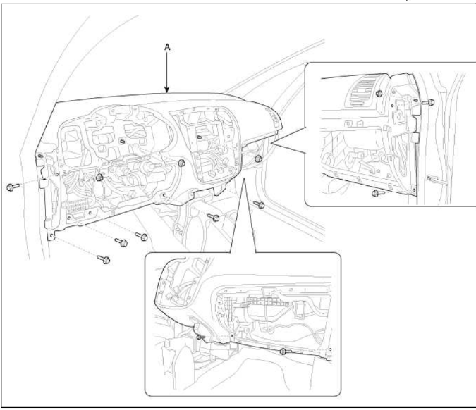
9. Installation is the reverse of removal.
NOTE
- Make sure the crash pad fits onto the guide pins correctly.
- Before tightening the bolts, make sure the crash pad wire harnesses are not pinched.
- Make sure the connectors are plugged in properly, and the antenna lead is connected properly.
- Enter the anti-theft code for the radio, then enter the customer's radio station presets
Cowl Cross Bar Replacement
CAUTION
- When prying with a flat-tip screwdriver, wrap it with protective tape, and apply protective tape around the related parts, to prevent damage.
- Put on gloves to protect your hands
1. Remove the following items.
- Front seat (Refer to the BD group - "Front Seat")
- Floor Console assembly (Refer to the BD group - "Console")
- Cowl top cover (Refer to the BD group - "Cowl Top Cover")
- Cowl side trim (Refer to the BD group - "Interior Trim")
- Main crash pad
2. Disconnect the blower unit connectors.
(Refer to the HA group - "Air conditioning system, Heater, Blower")
3. Disconnect the wiring connectors.
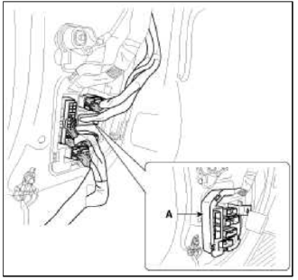
4. Using a screwdriver or remover, remove the multi box (A).
[Driver's]
5. Disconnect the wiring connectors.
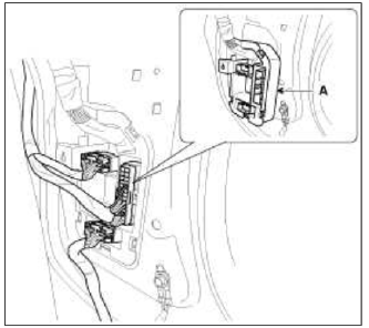
6. Using a screwdriver or remover, remove the multi box (A).
[Passenger's]
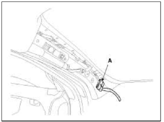
7. Disconnect the connectors (A).
8. Disconnect the airbag control module (SRSCM) connector (A).
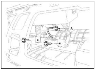
9. Disconnect the connector (A) and the mounting clips in the driver's front pillar.
10. After loosening the mounting bolts and nuts, then remove the cowl cross bar (A).
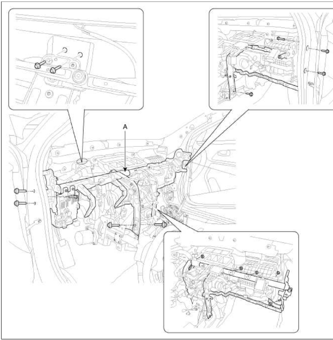
11. Installation is the reverse of removal.
NOTE
- Replace any damage clips.
- Make sure the connectors are plugged in properly.
READ NEXT:
 Roof Trim
Components and Components Location
Components
Roof trim
Sunvisor [Driver's]
Sunvisor [Passenger's]
Components [Panoramaroof]
Roof trim
Sunvisor [Driver's]
Interior Trim
Components and Components Location
Components
Front pillar trim
Center pillar upper trim
Center pillar lower trim
Luggage side trim
Cowl side trim
Front door scuff trim
Rear d
Windshield Glass
Components and Components Location
Components
Windshield side
molding
Windshield glass
Repair procedures
Replacement
Removal
CAUTION
Put on gloves to protect your hand
SEE MORE:
RCV Control Solenoid Valve | Canister Close Valve (CCV)
Description and Operation
Description
RCV (Recirculation Valve) Control Solenoid Valve is installed on the intercooler inlet pipe and operates the RCV actuator which controls the by-pass passage of the turbocharger compressor.
When the throttle is closed, while the engine is running at cru
Vehicle Auto Shut-off system
If your vehicle is parked and the engine
is left on for a long period of time, the
engine will turn off automatically to help
reduce fuel consumption and prevent
accidents caused by carbon dioxide poisoning.
Operating Conditions
Vehicle Auto-Shut Off timer operates
when all the following cond
Content
- Home
- Kia Sportage - Fifth generation (NQ5) - (2022-2026) - Owner's Manual
- Kia Sportage - Second generation (JEKM) (2005-2015) - Body Workshop Manual
- Kia Sportage Third generation (SL) - (2011-2016) - Service and Repair Manual
- Sitemap
- Top articles
