Kia Sportage: Cruise Control Switch
Schematic Diagrams
Circuit Diagram
[Auto Cruise Control]
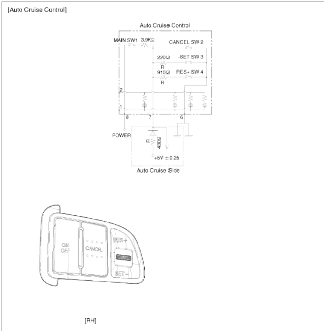
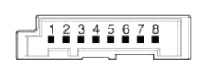 Connector RH
- ILL (-)
- ILL (+)
- -
- -
- -
- ACC GND
- ACC signal
- ACC power
Repair procedures
Removal and Installation
1. Disconnect the battery (-) terminal.
Tightening torque:
Without battery sensor: 7.8 ~ 9.8N.m (0.8 ~ 1.0.kgf.m, 5.8 ~ 7.2lb-ft)
With battery sensor: 4.0 ~ 6.0N.m (0.4 ~ 0.6kgf.m, 3.0 ~ 4.4lb-ft)
2. Remove the airbag module from the steering wheel. (Refer to RT group)
3. Remove the steering wheel. (Refer to ST group)
4. Remove the cruise control switch (A) after unfastening the 2 screws and disconnecting the switch connector.
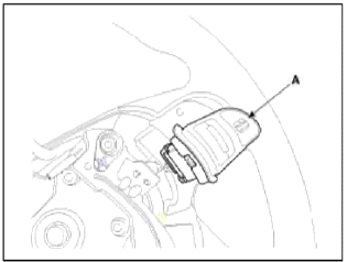
5. Installation is reverse order of removal.
Inspection
Measuring Resistance
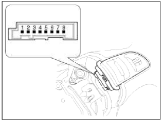
1. Disconnect the cruise control switch connector from the control switch.
2. Measure resistance between terminals on the control switch when each function switch is ON (switch is depressed).
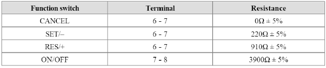
3. If not within specification, replace switch.
Measuring Voltage
1. Connect the cruise control switch connector to the control switch.
2. Measure voltage between terminals on the harness side connector when each function switch is ON (switch is depressed).
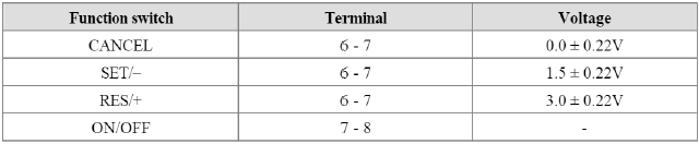
3. If not within specification, inspect the control switch resistance.
The measuring resistance value is not within specification, replace the switch and measure the voltage again.
4. If resistance is OK but, measuring voltage is not within specification, inspect the wiring harness and connectors between the switch and the ECM.
READ NEXT:
 General Information
Specifications
Specifications
Tightening Torques
Repair procedures
Compression Pressure Inspection
NOTE
If the there is lack of power, excessive oil consumption or poor
Engine And Transaxle Assembly
Engine Mounting
Components and
Components Location
Components
Transaxle mounting bracket
Roll rod bracket
Sub frame
Engine mounting bracket
Engine mounting support
bracket
SEE MORE:
Schematic Diagrams, Repair procedures | Positive Crankcase Ventilation (PCV) Valve
Schematic Diagrams
Schematic Diagram
Repair procedures
Inspection
1. After disconnecting the vapor hose from the PCV valve, remove the PCV valve.
2. Reconnect the PCV valve to the vapor hose.
3. Run the engine at idle, then put a finger over the open end of the PCV valve and make sur
Start/Stop Button | Fob Holder
Components and Components Location
Component
Connector (10 pins)
Start stop button switch 1
LED illumination power
Amber LED
Start stop button illumination GND
Start stop button illumination Power
Ground
Start stop button switch 2
Green LED
R
Content
- Home
- Kia Sportage - Fifth generation (NQ5) - (2022-2026) - Owner's Manual
- Kia Sportage - Second generation (JEKM) (2005-2015) - Body Workshop Manual
- Kia Sportage Third generation (SL) - (2011-2016) - Service and Repair Manual
- Sitemap
- Top articles
