Kia Sportage: Reassembly - Repair procedures
NOTE
- Thoroughly clean all parts to assembled.
- Before installing the parts, apply fresh engine oil to all sliding and rotating surfaces.
- Replace all gaskets, O-rings and oil seals with new parts.
1. Assemble the piston and connecting rod.
- The piston front mark and the connecting rod front mark must face the timing chain side of the engine.
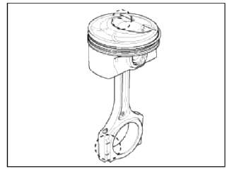
- Before pressing the piston pin, apply a coat of lubricant oil to the piston pin outer and connecting rod.
CAUTION
- Take care that piston pin is not damaged dining reassemble.
- When replace the piston pin, check the piston pin outer diameter and connecting rod small end inner diameter as below.
Piston pin outer diameter : 21.997 ~ 22.000mm (0.8660 - 0.8661in)
Piston pin hole inner diameter: 22.003mm - 22.007mm (0.8662 ~ 0.8664in)
Connecting rod small end inner diameter : 22.005 ~ 22.011 mm (0.8663 ~ 0.8665in)
Interference : -0.014mm ~ -0.005mm (0.0006 ~ 0.0002in)
- Set the snap ring in one side of piston pin hole and insert the piston pin into the piston pin hole & the small end bore of connecting rod while meeting the front mark of connecting rod & piston.
CAUTION
Be sure to keep the small end bore, piston pin hole & piston pin from being damaged and scratched when inserting the piston pin.
NOTE
Assembling condition
Temperature: piston side 70 to 80C, connecting rod & pin is to be normal room temperature.
- After inserting the piston pin, set the snap ring of the other side.
CAUTION
Set the snap ring so that it contacts completely with the groove of the piston pin hole.
The snap ring must not be deformed from the installation tooling method.
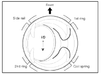
2. Install the piston rings.
- Install the oil ring with coil spring by hand.
- Using a piston ring expander, install the 2 compression rings with the code mark facing upward.
- Position the piston rings so that the ring ends are as shown.
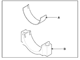
3. Install the connecting rod bearings.
- Align the bearing claw with the groove of the connecting rod or connecting rod cap.
- Install the bearings (A) in the connecting rod and connecting rod cap (B).
4. Install the main bearings.
NOTE
Upper bearings have an oil groove of oil holes; Lower bearings do not.
- Align the bearing claw with the claw groove of the cylinder block, push in the 5 upper bearings (A).
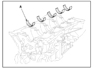
- Align the bearing claw with the claw groove of the main bearing cap, and push in the 5 lower bearings.
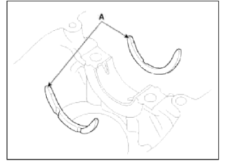
5. Install the thrust bearings.
Install the 2 thrust bearings (A) under the No.3 journal position of the cylinder block with the oil grooves facing outward.
6. Install the oil jet (A).
Tightening torque 24.5 ~ 29.4N.m (2.5 ~ 3.0kgf.m, 18.1 ~ 21.7lb-ft)
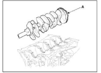
7. Place the crankshaft (A) on the cylinder block.
8. Place the main bearing caps on cylinder block.
9. Install the main bearing cap bolts.
CAUTION
Always use new main bearing cap bolts.
NOTE
- The main bearing cap bolts are tightened in 3 progressive steps.
- If any of the bearing cap bolts in broken or deformed, replace it.
- Apply a light coat of engine oil on the threads and under the bearing cap bolts.
- Using the SST (09221-4A000), install and uniformly tighten the 10 bearing cap bolts, in several passes, in the sequence shown.
Tightening torque 14.7N.m (1.5kgf.m, 10.8lb-ft) + 27.5~31.4N.m (2.8~3.2kgf.m, 20.3~23.1lb-ft) + 120~125º
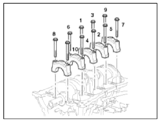
- Check that the crankshaft turns smoothly.
10. Check crankshaft end play.
11. Install piston and connecting rod assemblies
NOTE
Before installing the pistons, apply a coat of engine oil to the ring grooves and cylinder bores.
- Remove the connecting rod caps, and slip short sections of rubber hose over the threaded ends of the connecting rod bolts.
- Install the ring compressor, check that the bearing is securely in place, then position the piston in the cylinder, and tap it in using the wooden handle of a hammer.
- Stop after the ring compressor pops free, and check the connecting rod-to-check journal alignment before pushing the piston into place.
- Apply engine oil to the bolt threads. Using the SST (09221-4A000), install the rod caps with bearings, and torque the bolts.
Tightening torque 17.7~21.6N.m (1.8~2.2kgf.m. 13.0~15.9lb-ft) + 88~92º
CAUTION
Always use new connecting rod cap bolts.
NOTE
Maintain downward force on the ring compressor to prevent the lings from expanding before entering the cylinder bore.
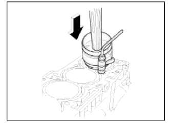
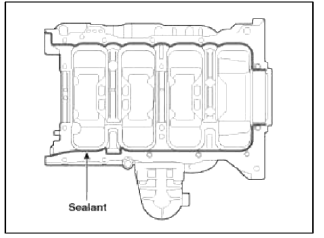
12. Apply liquid gasket to the mating surface of cylinder block and ladder frame.
NOTE
- When assembling ladder frame, the liquid sealant Loctite 5900H, Threebond 1217H or equivalent should be applied ladder frame.
- The part must be assembled within 5 minutes after sealant was applied.
- Apply sealant to the inner threads of the bolt holes.
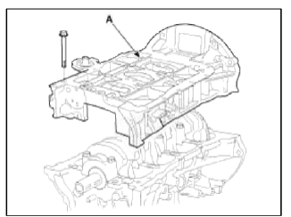
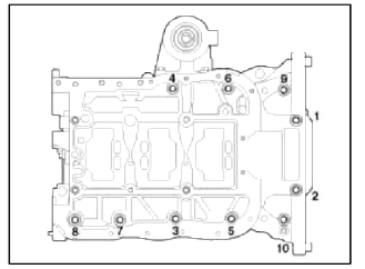
13. Install ladder frame (A) with 10 bolts, in several passes, in sequence shown.
Tightening torque
Step 1 :8.8 ~ 9.8N.m (0.9~ 1.0kgf.m, 6.5 ~ 7.2lb-ft)
Step 2 : 17.7 ~20.6N.m (1.8 ~ 2.1kgf.m, 13.0 ~ 15.2lb-ft)
Step 3 : 27.5 ~ 31.4N.m (2.8 ~ 3.2kgf.m, 20.3 ~ 23.1lb-ft)
- Tighten the bolts in order number as shown with the 3 steps.
- Loosen the bolts as reverse tightening order.
- Tighten the bolts in order number as shown with the 3 steps.
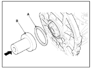
14. Install rear oil seal.
- Apply engine oil to a new oil seal lip.
- Using SST(09231-H1100.09214-3K100) (B) and a hammer, tap in the oil seal (A) until its surface is flush with the rear oil seal retainer edge.
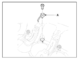
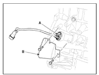
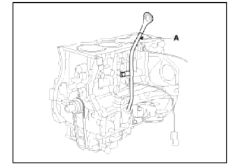
15. Install CKPS (Crankshaft position sensor) (A) and sensor cover (B).
Tightening torque 9.8 ~ 11.8N.m (1.0 ~ 1.2kgf.m, 7.2 ~ 8.7lb-ft)
16. Install oil pressure switch.
- Apply adhesive to 2 or 3 threads.
Adhesive : MS 721-39(B) or equivalent.
- Install the oil pressure switch (A).
Tightening torque 7.8 ~ 11.8N.m (0.8 ~ 1.2kgf.m, 5.8 ~ 8.7lb-ft)
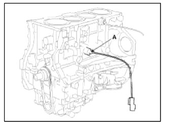
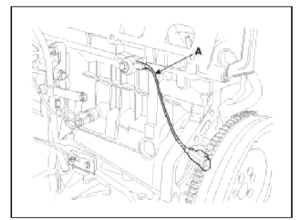
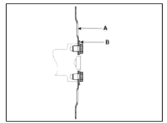
17. Install knock sensor (A).
Tightening torque 18.6 ~ 23.5N.m (1.9 ~ 2.4kgf.m, 13.7 ~ 17.4lb-ft)
18. Install oil level gauge assembly.
- Install a new O-ring on the oil level gauge.
- Apply engine oil on the O-ring.
- Install the oil level gauge assembly (A) with the bolt.
Tightening torque 7.8 ~ 11.8N.m (0.8 ~ 1.2kgf.m, 5.8 ~ 8.7lb-ft)
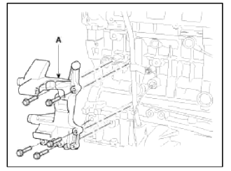
19. Install tensioner assembly integrated bracket (A).
Tightening torque 39.2 ~ 44.1N.m (4.0 ~ 4.5kgf.m, 28.9 ~ 32.5lb-ft)
20. Install the water pump. (Refer to Cooling system in this group)
21. Install the alternator. (Refer to EE group)
22. Install the balance shaft & oil pump assembly. (Refer to Lubrication system in this group)
23. Install the cylinder head assembly. (Refer to Cylinder head in this group)
24. Install the timing chain. (Refer to Timing system in tins group)
25. Install the intake manifold and exhaust manifold.
(Refer to Intake and exhaust system in this group)
26. Remove the engine from the engine stand.
27. Install the drive plate (A) and the adapter plate (B).
Tightening torque: 117.7 ~ 127.5N.m (12.0 ~ 13.0kgf.m, 86.8 ~ 93.9lb-ft)
NOTE
- Always use new drive plate bolts.
- Apply sealant to the screw part (10mm from the end of the bolt) when reusing the drive plate bolts.
Sealant: Three bond 2403, Loctite 200 or 204
- Install and uniformly tighten the 7 bolts, in several passes
28. Install the engine assembly on the vehicle.
(Refer to Engine and transaxle assembly in this group)
Add all thirds to their normal operating levels.
READ NEXT:
 Coolant
Repair procedures
Refilling And Bleeding
WARNING
Never remove the radiator cap when the engine is hot. Serious scalding
could be caused by hot fluid under high
pressure escaping from the radiato
Radiator
Components and Components Location
Components
Cooling fan assembly
Radiator assembly
Mounting insulator
Radiator mounting
bracket
Radiator upper hose
Radiator lower hose
Res
SEE MORE:
General Information
Specifications
Specifications
Ignition System
Starting System
Charging System
CAUTION
COLD CRANKING AMPERAGE is the amperage a battery can deliver for 30
seconds and maintain a
terminal voltage of 7.2V or greater at a specified temperature.
RESERVE CAPACITY RATING is amou
Front Cross Member
Repair procedures
Replacement
1. Remove the front wheel & tire.
Tightening torque:
88.3 ~ 107.9N.m (9.0 ~ 11.0kgf.m, 65.1 ~ 79.6lb-ft)
CAUTION
Be careful not to damage to the hub bolts when removing the front wheel &
tire (A).
2. Disconnect the stabilizer link (B) from the f
Content
- Home
- Kia Sportage - Fifth generation (NQ5) - (2022-2026) - Owner's Manual
- Kia Sportage - Second generation (JEKM) (2005-2015) - Body Workshop Manual
- Kia Sportage Third generation (SL) - (2011-2016) - Service and Repair Manual
- Sitemap
- Top articles
