Kia Sportage: Engine And Transaxle Assembly
Engine Mounting
Components and Components Location
Components
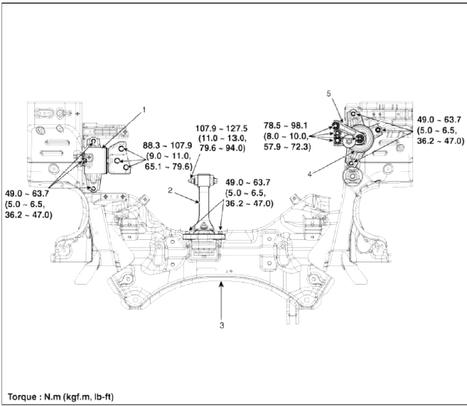
- Transaxle mounting bracket
- Roll rod bracket
- Sub frame
- Engine mounting bracket
- Engine mounting support bracket
Engine And Transaxle Assembly
Repair procedures
Removal
CAUTION
- Use fender covers to avoid damaging painted surfaces.
- To avoid damage, unplug the wiring connectors carefully while holding the connector portion.
NOTE
- Mark all wiring and hoses to avoid misconnection.
- To release the fuel system pressure before removing the engine assembly, start the engine with the fuel pump relay removed. And then turn off the ignition switch after engine stops.
1. Remove the engine cover.
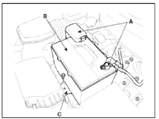
2. Disconnect the battery terminals (A).
Tightening torque:
(+) terminal: 7.8 ~ 9.8N.m (0.8 ~ 1.0kgf.m, 5.8 ~ 7.2lb-ft)
(-) terminal: 4.0 ~ 6.0N.m (0.4 ~ 0.6kgf.m. 3.0 ~ 4.4lb-ft)
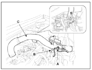
3. Remove the battery (B) after removing the mounting bracket (C).
Tightening torque: 8.8 ~ 13.7 N.m (0.9 ~ 1.4 kgf.m, 6.5 ~ 10.1 lb-ft)
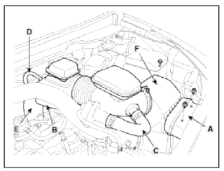
4. Remove the air cleaner assembly.
- Remove the air duct (A).
- Disconnect the breather hose (B), the recirculation hose (C) and the brake booster vacuum hose (D).
- Disconnect the air intake hose (E) and then remove the air cleaner assembly (F).
Tightening torque
Hose clamp bolt: 2.9 ~ 4.9N.m (0.3 ~ 0.5kgf.m, 2.2 ~ 3.6lb-ft)
Aft cleaner assembly bolts: 7.8 ~9.8N.m (0.8 ~ 1.0kgf.m, 5.8 ~ 7.2lb-ft)
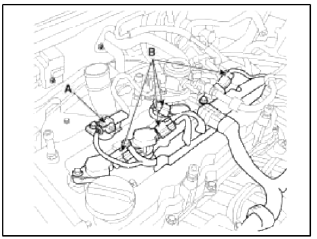
5. Remove the ECM (A) after disconnecting the connectors (B). (Refer to FL group)
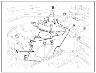
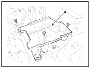
6. Remove the battery tray (A).
Tightening torque: 8.8 ~ 13.7 N.m (0.9 ~ 1.4 kgf.m, 6.5 ~ 10.1 lb-ft)
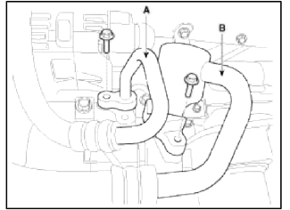
7. Disconnect the recirculation valve connector (A) and the vacuum hose (B), and then remove the intercooler inlet pipe & hose assembly (C).
Tightening torque
Hose clamp bolt: 4.9 ~ 6.9 N.m (0.5 ~ 0.7 kgf.m 3.6 ~ 5.1 lb-ft)
Pipe mounting bolt: 14.7 ~ 19.6 N.m (1.5 ~ 2.0 kgf.m 10.8 ~ 14.5 lb-ft)
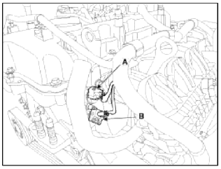
8. Disconnect the boost pressure sensor connector (A) and then remove the intercooler outlet pipe & hose assembly (B).
Tightening torque 4.9 ~ 6.9 N.m (0.5 ~ 0.7 kgf.m, 3.6 ~ 5.1 lb-ft)

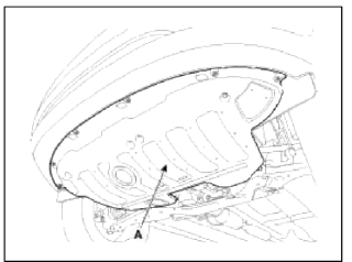
9. Remove the under cover (A).
Tightening torque: 9.8 ~ 11.8 N.m (1.0 ~ 1.2 kgf.m. 7.2 ~ 8.7 lb-ft)
10. Loosen the drain plug, and drain the engine coolant. Remove the radiator cap to drain with speed. (Refer to Cooling system in this group)
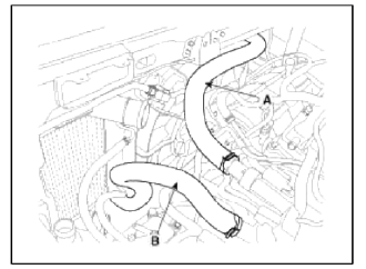
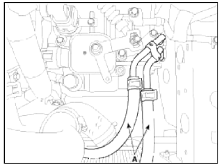
11. Disconnect the radiator upper hose (A) and lower hose (B).
12. Recover the refrigerant and then remove the high pressure pipe (A) and low pressure pipe (B). (Refer to Air conditioning system in HA Group.)
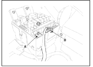
13. Disconnect the (+) cable (A) and connector (B) from the fuse/relay box.
14. Disconnect the wiring connectors and harness clamps, and remove the wiring protectors from the cylinder head, intake manifold and exhaust manifold.
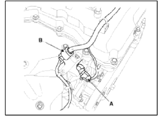
- Disconnect the exhaust OCV (Oil control valve) connector (A) and the oxygen sensor connector (B).
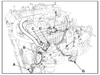
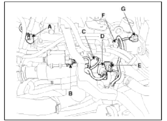
- Disconnect the Ð/С compressor switch connector (A), the alternator connector (B), the OPS (Oil pressure switch) connector & injector extension connector (C), the knock sensor connector (D), the MAPS (Manifold absolute pressure sensor) & IATS (Intake air temperature sensor) connector (E), the ETC (Electronic throttle control) connector (F) and the vacuum pump connector (G).
- Disconnect the ignition coil connectors (B) and the fuel pump connector (A).
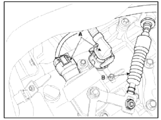
- Disconnect the intake OCV (Oil control valve) connector (A) and the OTS (Oil temperature sensor) connector (B).
- Disconnect the intake CMPS (Camshaft position sensor) connector (A), the PCSV (Purge control solenoid valve) connector (B), the ECTS (Engine coolant temperature sensor) connector (C), the condenser connector (D), the CKPS (Crankshaft position sensor) connector (E), the exhaust CMPS (Camshaft position sensor) connector (F) and the electric wastegate actuator connector (G).
15. Remove the transaxle wire harness connectors (A) and control cable (B) from the transaxle. (Refer to AT group).
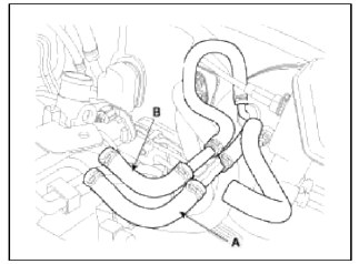
16. Disconnect the ATF cooler hoses (A).
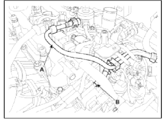
17. Disconnect the intensifier hose (A) and the vacuum hose (B).
18. Disconnect the fuel hose (A) and PCSV (Purge control solenoid valve) hose (B).
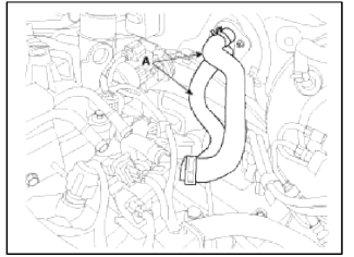
19. Disconnect the heater hoses (A).
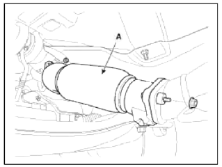
20. Remove the front muffler (A).
Tightening torque: 39.2 ~ 58.8 N.m (4.0 ~ 6.0 kgf.m, 28.9 ~ 43.4 lb-ft)
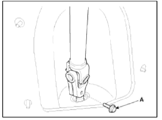
21. Remove the steering u-joint mounting bolt (A). (Refer to ST group)
22. Remove the front wheels.
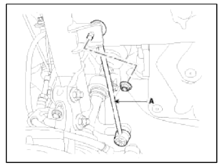
23. Remove the lower arms (A). (Refer to SS group)
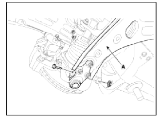
24. Remove the stabilizer bar links (A). (Refer to SS group)
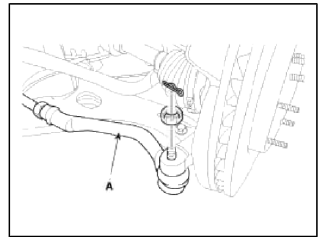
25. Remove the tie rod ends (A). (Refer to ST group)
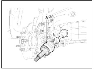
26. Disconnect the drive shafts (A) from the axle hubs. (Refer to DS group)
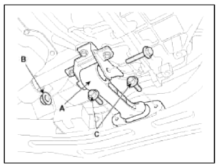
27. Remove the roll rod bracket (A).
Tightening torque:
Nut (B ): 88.3 ~ 107.9 N.m (9.0 -11.0 kgf.m, 65.1 ~ 79.6 lb-ft)
Bolts (C): 49.0 ~ 63.7 N.m (5.0 ~ 6.5 kgf.m. 36.2 ~ 47.0 lb-ft)
28. Support the sub frame (A) with a floor jack, and then remove the sub frame mounting bolts and nuts.
Tightening torque:
176.5 ~ 196.1 N.m (18.0 ~ 20.0 kgf.m. 130.2 ~ 144.7 lb-ft)
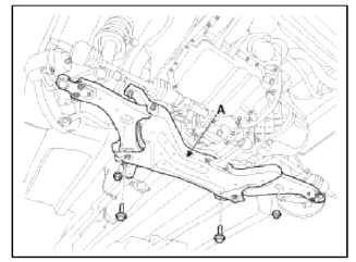
NOTE
- After removing the sub frame mounting bolt, the engine and transaxle assembly may fall downward, and so support them securely with floor jack.
- Verify that the hoses and connectors are disconnected before removing the engine and transaxle assembly.
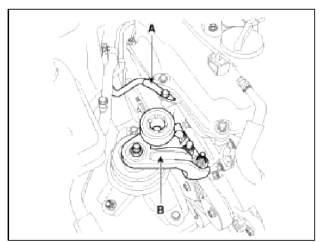
29. Disconnect the ground line (A), and then remove the engine mounting support bracket (B).
Tightening torque: 78.5 ~ 98.1 N.m (8.0 ~ 10.0 kgf.m 57.9 ~ 72.3 lb-ft)
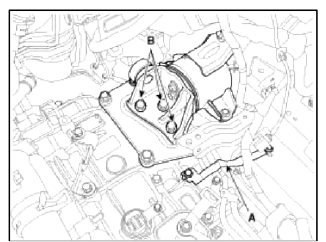
30. Disconnect the ground line (A), and then remove the transaxle mounting support bracket (B).
Tightening torque: 88.3 ~ 107.9 N.m (9.0 ~ 11.0 kgf.m. 65.1 ~ 79.6 lb-ft)
31. Remove the engine and transaxle assembly by lifting vehicle.
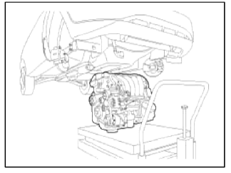
CAUTION
When remove the engine and transaxle assembly, be careful not to damage any surrounding parts or body components.
Installation
Installation is in the reverse order of removal.
Perform the following:
- Adjust a shift cable.
- Refill engine with engine oil.
- Refill a transaxle with fluid.
- Refill a radiator and a reservoir tank with engine coolant.
- Clean battery posts and cable terminals and assemble.
- Inspect for fuel leakage.
- After assemble the fuel line, turn on the ignition switch (do not operate the starter) so that the fuel pump runs for approximately two seconds and fuel line pressurizes.
- Repeat this operation two or three times, then check for fuel leakage at any point in the fuel line.
- Bleed air from the cooling system.
- Start engine and let it run until it warms up. (until the radiator fan operates 3 or 4 times.)
- Turn Off the engine. Check the level in the radiator, add coolant if needed. This will allow trapped air to be removed from the cooling system.
- Put radiator cap on tightly, then run the engine again and check for leaks.
READ NEXT:
 Components and Components Location | Removal - Repair procedures
Components
Intake camshaft
Exhaust camshaft
Intake CVVT assembly
Exhaust CVVT assembly
Timing chain
Timing chain guide
Timing chain tensioner arm
Timi
SEE MORE:
Lane Following Assist settings
Lane Following Assist is designed to help
detect lane markings and/or vehicles on
the road, and assists the driver's steering
to help keep the vehicle between lanes.
Detecting sensor
Front view camera
The front view camera is used as a
detecting sensor to detect lane markings
and fro
Securing a child restraint with a
lap/shoulder belt
When not using the LATCH system, all
child restraints must be secured to a
vehicle rear seat with the lap part of a
lap/shoulder belt.
Automatic locking mode
All passenger seat belts move
freely
under normal conditions and only lock
under extreme or emergency conditions
(emergency locking
Content
- Home
- Kia Sportage - Fifth generation (NQ5) - (2022-2026) - Owner's Manual
- Kia Sportage - Second generation (JEKM) (2005-2015) - Body Workshop Manual
- Kia Sportage Third generation (SL) - (2011-2016) - Service and Repair Manual
- Sitemap
- Top articles
