Kia Sportage: General Information
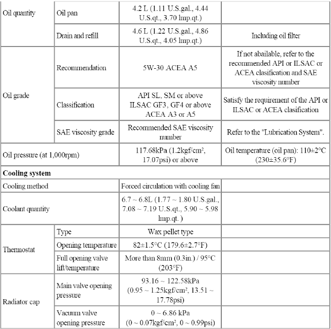
Specifications
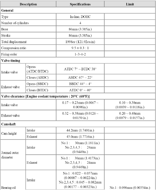
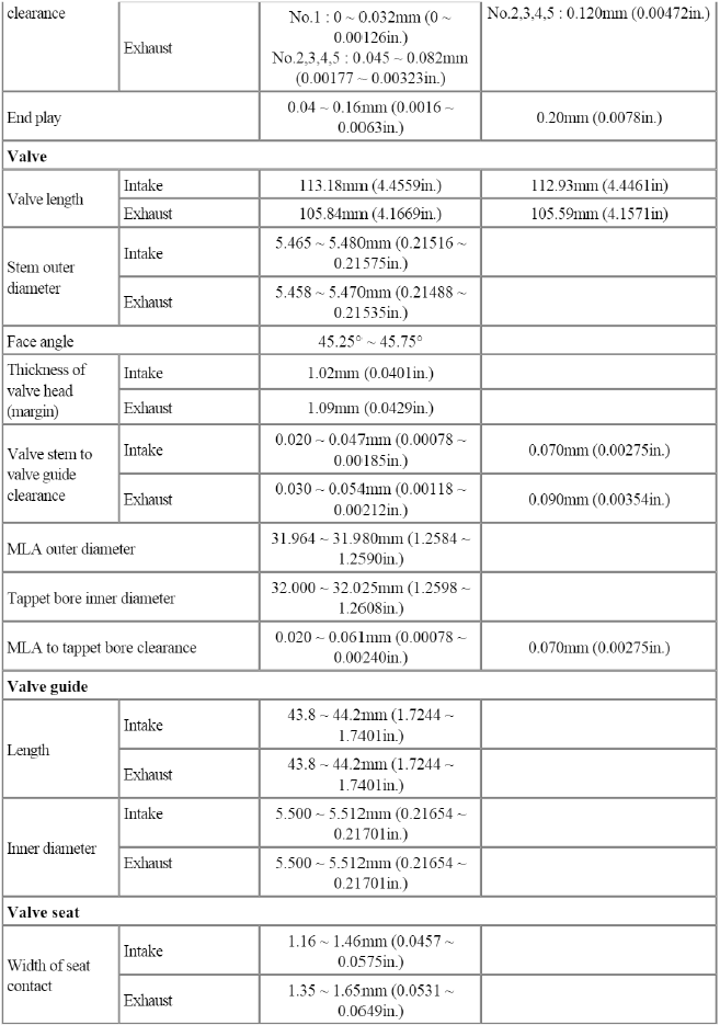
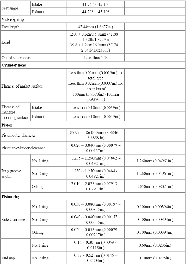
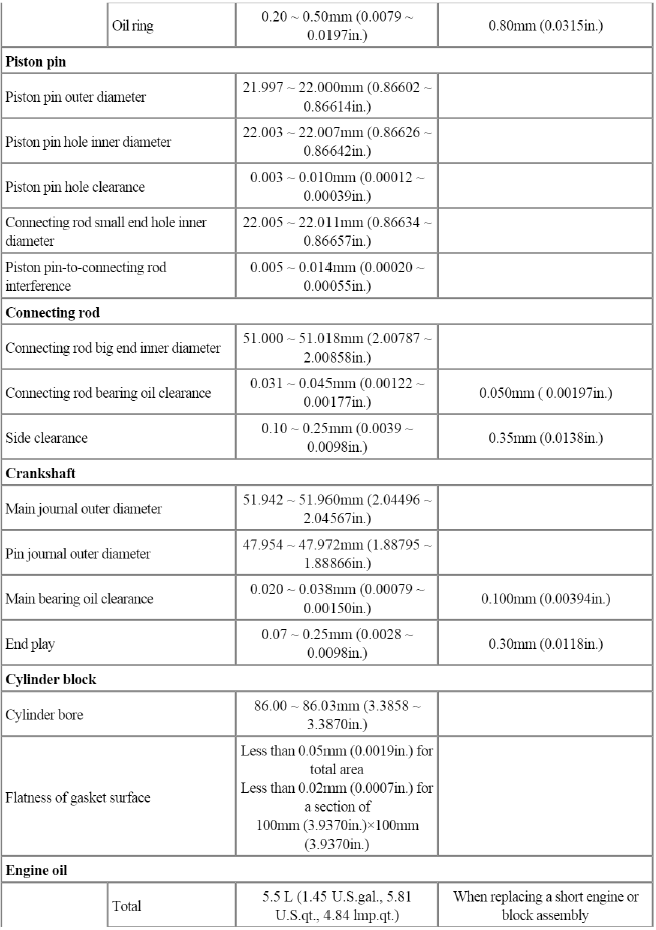
Specifications
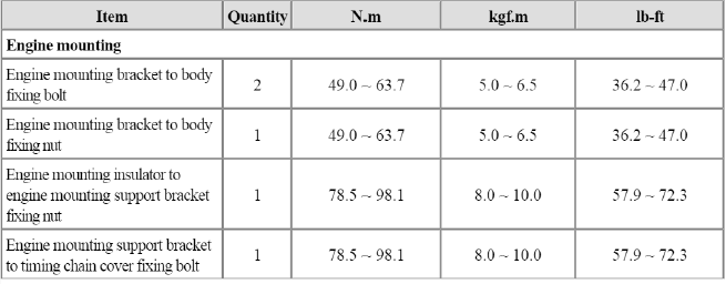
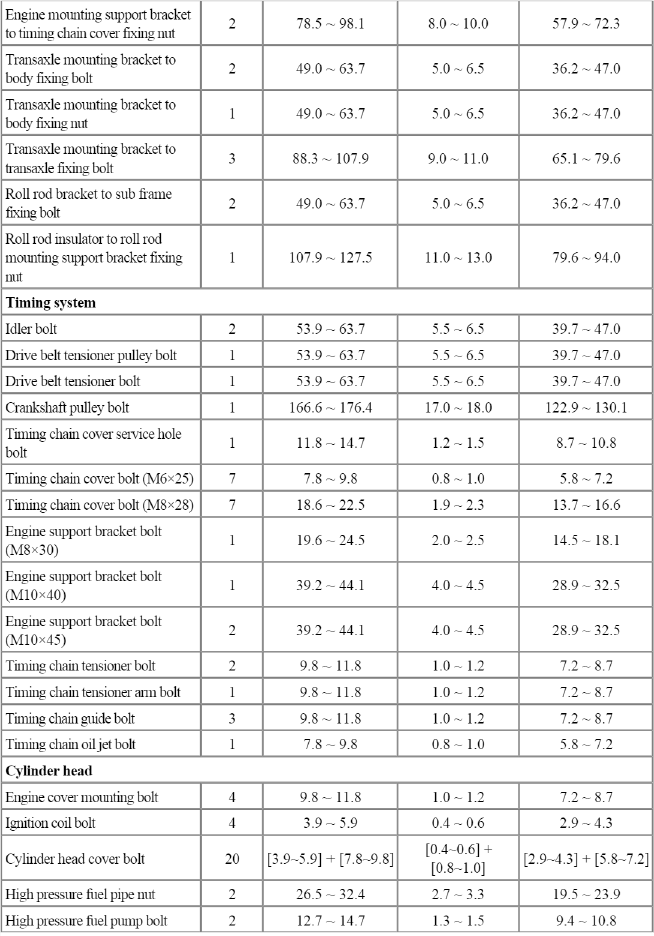
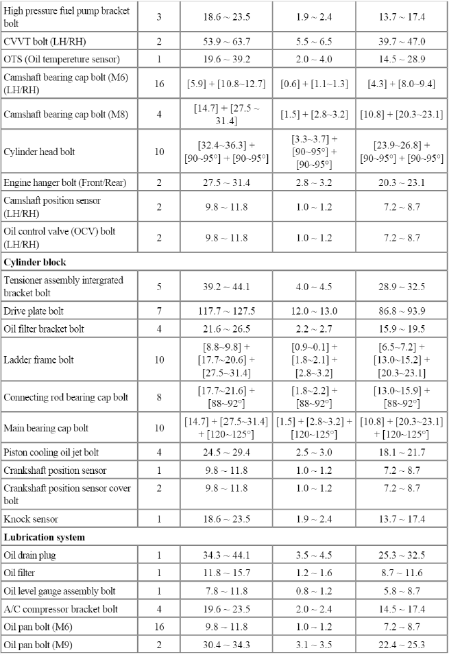
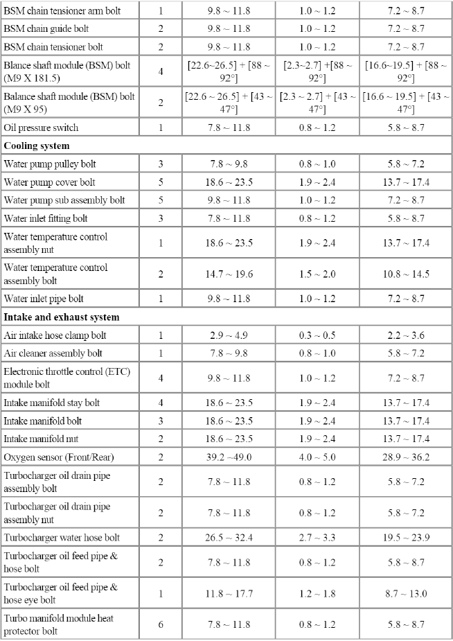
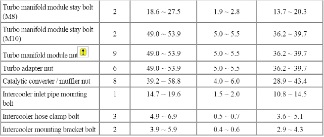
Tightening Torques
Repair procedures
Compression Pressure Inspection
NOTE
If the there is lack of power, excessive oil consumption or poor fuel economy, measure the compression pressure.
1. Warm up and stop engine.
Allow the engine to warm up to normal operating temperature.
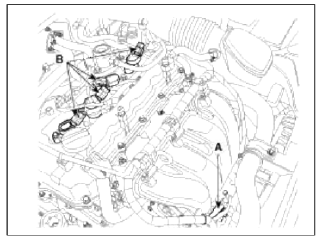
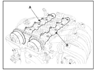
2. Disconnect the injector extension connector (A) and ignition coil connectors (B).
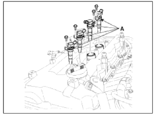
3. Remove ignition coils (A).
4. Remove spark plugs.
Using a 16mm plug wrench, remove the 4 spark plugs.
5. Check cylinder compression pressure.
- Insert a compression gauge into the spark plug hole.
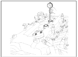
- Fully open the throttle.
- While cranking the engine, measure the compression pressure.
NOTE
Always use a fully charged battery to obtain engine speed of 200 rpm or more.
- Repeat steps (1) through (3) for each cylinder.
NOTE
This measurement must be done in as short a time as possible.
Compression pressure : l,324kPa (13.5kgf/cm2, 192psi) / 200 ~ 250rprn
Minimum pressure: l,177kPa (12.0kgf/cm2,171psi)
Difference between each cylinder : 100кРа (1.0kgf/cm2,15psi) or less
- If the cylinder compression in 1 or more cylinders is low, pour a small amount of engine oil into the cylinder though the spark plug hole and repeat steps (1) through (3) for cylinders with low compression.
- If adding oil helps the compression, it is likely that the piston lings and/or cylinder bore are worn or damaged.
- If pressure stays low, a valve may be sticking or seating is improper, or there may be leakage past the gasket.
6. Reinstall spark plugs.
7. Install ignition coils.
8. Connect the injector extension connector and ignition coil connectors.
9. Some DTC's may exist after the inspection test and may need to be manually cleared with GDS.
Valve Clearance Inspection And Adjustment
NOTE
Inspect and adjust the valve clearance when the engine is cold (Engine coolant temperature : 20ºC (68ºF) ) and cylinder head is installed on the cylinder block.
WARNING
In case of removing the high pressure fuel pump, high pressure fuel pipe, delivery pipe, and injector, there may be injury caused by leakage of the high pressure fuel. So don't do any repair work right after engine stops.
1. Remove the cylinder head cover. (Refer to Timing system in this group)
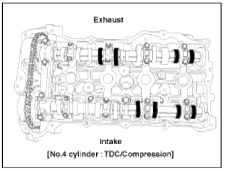
2. Set No. cylinder to TDC/compression.
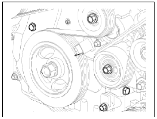
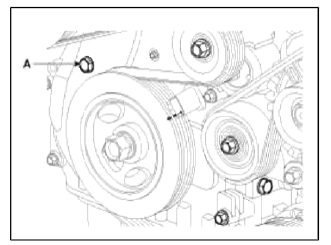
- Turn the crankshaft pulley and align its groove with the timing mark "T" of the lower timing chain cover.
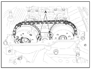
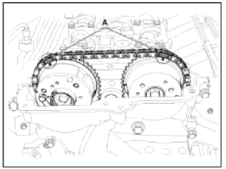
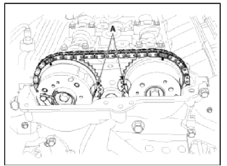
- Check that the TDC marks (A) of the C W T sprockets are in straight line
on the cylinder head surface as
shown in the illustration.
If not, turn the crankshaft one revolution (360º)
3. Inspect the valve clearance.
- Check only the valve indicated as shown. Measure the valve clearance.
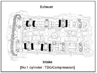
- Using a thickness gauge, measure the clearance between the tappet and the base circle of camshaft.
- Record the out-of-specification valve clearance measurements. They will be used later to determine the required replacement adjusting tappet.
Valve clearance
Specification
Engine coolant temperature: 20ºC [68ºF]
Limit
Intake : 0.10 ~ 0.30mm (0.0039 ~ 0.0118in.)
Exhaust: 0.20 ~ 0.40mm (0.0079 ~ 0.0157in.)
- Turn the crankshaft pulley one revolution (360º) and align the groove with timing mark "T" of the lower timing chain cover.
- Check only valves indicated as shown. Measure the valve clearance.
4. Adjust the intake and exhaust valve clearance.
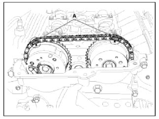
- Set the No.1 cylinder to the TDC/compression.
- Mark the timing chains (A) on the timing marks of the CVVT sprockets.
- Remove the front camshaft bearing cap.
- Turn the crankshaft pulley 15º clockwise.
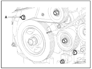
- Remove the service hole bolt (A) of the timing chain cover.
CAUTION
The bolt must not be reused once it has been assembled.
- Remove the intake and exhaust camshaft bearing caps.
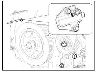
- Release the ratchet of the timing chain tensioner by pulling the link down using a thin rod.
- After loosening the timing chain, remove the exhaust CVVT & camshaft assembly (A) and then the intake CVVT & camshaft assembly (B).
CAUTION
When disconnect the timing chain from the CVVT sprocket, hold the timing chain.
- Tie down tuning chain so that it doesn't move.
CAUTION
Be careful not to drop anything inside tuning chain cover.
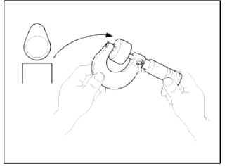
- Measure the thickness of the removed tappet using a micrometer.
- Calculate the thickness of a new tappet so that the valve clearance conies within the specified value.
Valve clearance [Engine coolant temperature : 20ºC (68ºF) ]
T : Thickness of removed tappet
A : Measured valve clearance
N : Thickness of new tappet
Intake : N = T + [A - 0.20mm (0.0079in.) ]
Exhaust: N = T + [A - 0.30mm (0.0118in.) ]
- Select a new tappet with a thickness as close as possible to the calculated value.
NOTE
Shims are available in 47 size increments of 0.015mm (0.0006m.) from 3.00mm. (0.118in.) to 3.690mm (0.1452in.)
- Place a new tappet on the cylinder head.
- Hold the timing chain, and place the intake CVVT & camshaft assembly.
- Place the exhaust CVVT & camshaft assembly after releasing the ratchet of the timing chain tensioner.
NOTE
The timing marks of each CVVT sprocket should be matched with timing marks (painted link) of timing chain when installing the timing chain.
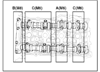
- Install the camshaft bearing caps in then proper locations.
Tightening order
Group A → Group В → Group C
Tightening torque
Step 1
M6 : 5.9N.m (0.6kgf.m, 4.3lb-ft)
M8 : 14.7N.m (1.5kgf.m, 10.8lb-ft)
Step 2
M6 : 10.8 ~ 12.7N.m (1.1 ~ 1.3kgf.m, 8.0 ~ 9.4lb-ft)
M8 : 27.5 ~ 31.4N.m (2.8 ~ 3.2kgf.m, 20.3 ~ 23.1lb-ft)
- Install the service hole bolt (A).
Tightening torque: 11.8 ~ 14.7N.m (1.2 ~ 1.5kgf.m, 8.7 ~ 10.8lb-ft)
- Turn the crankshaft two turns in the operating direction (clockwise), and then check that the TDC marks (A) of the CVVT sprockets are in straight line on the cylinder head surface.
- Recheck the valve clearance.
Valve clearance [Engine coolant temperature : 20ºC (68ºF) ]
[Specification]
Intake : 0.17 ~ 0.23mm (0.0067 ~ 0.0090 in.)
Exhaust: 0.32 ~ 0.38mm (0.0126 ~ 0.0150 in.)
- Install the cylinder head cover. (Refer to Timing system in this group
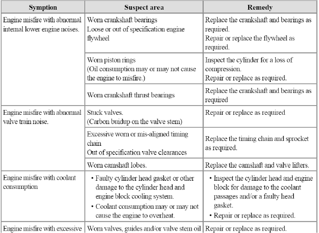
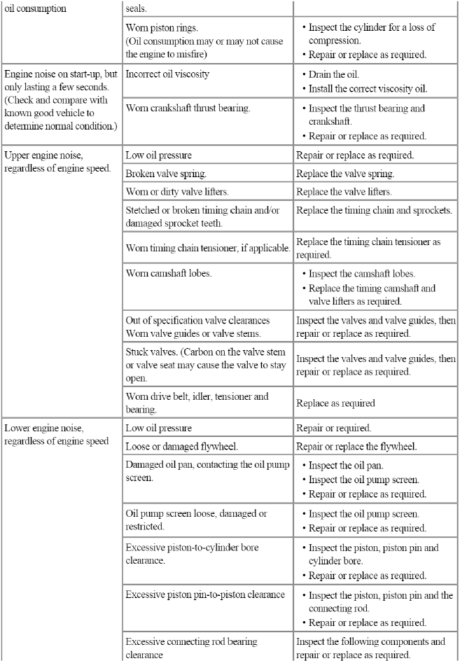
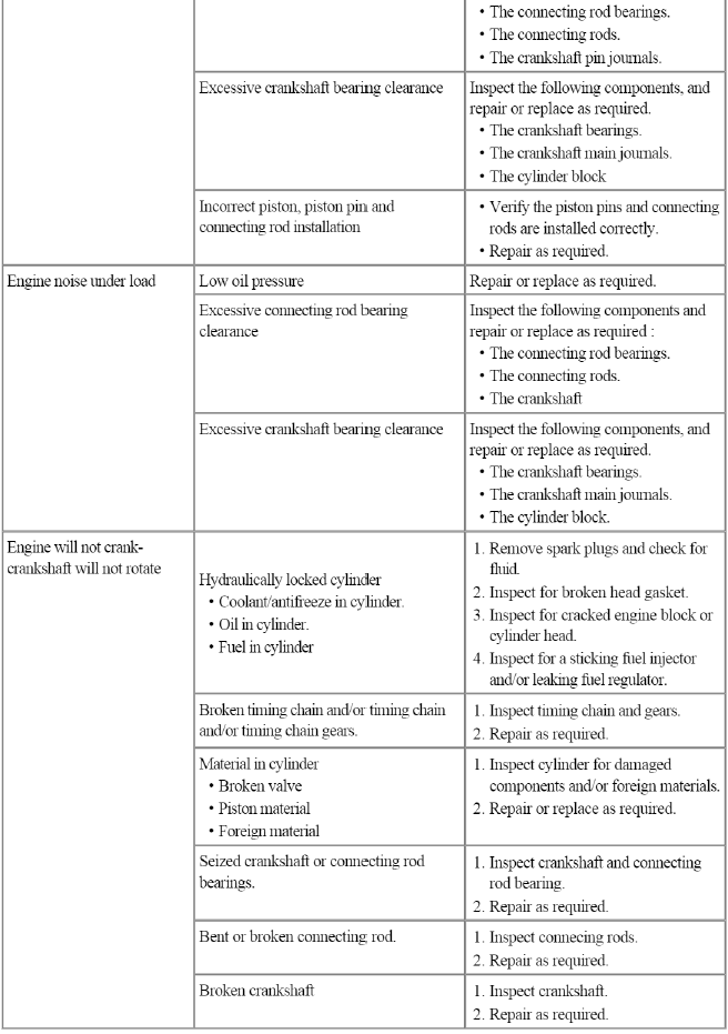
Troubleshooting
Troubleshooting
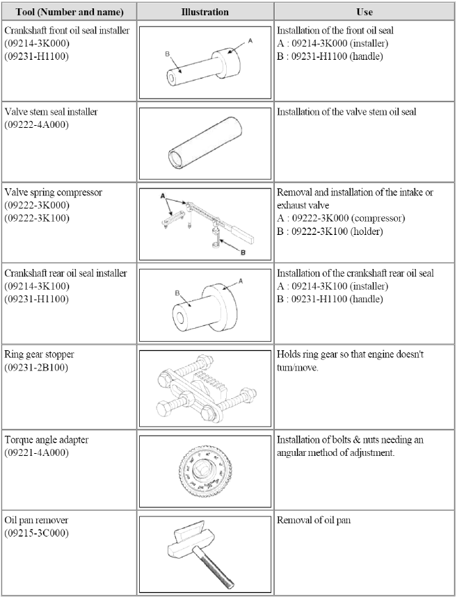
Special Service Tools
Special Service Tools
READ NEXT:
 Engine And Transaxle Assembly
Engine Mounting
Components and
Components Location
Components
Transaxle mounting bracket
Roll rod bracket
Sub frame
Engine mounting bracket
Engine mounting support
bracket
Components and Components Location | Removal - Repair procedures
Components
Intake camshaft
Exhaust camshaft
Intake CVVT assembly
Exhaust CVVT assembly
Timing chain
Timing chain guide
Timing chain tensioner arm
Timi
SEE MORE:
Condenser | Receiver-Drier
Components and Components Location
Component Location
Repair procedures
Inspection
1. Check the condenser fins for clogging and damage. If clogged, clean them with water, and blow them with compressed air. If bent, gently bend them using a screwdriver or pliers.
2. Check the condenser
Air bag non-inflation conditions
Air bags may not deploy in certain
low-speed collisions where the air bag
would not add any benefit beyond the
protection already offered by the seat
belts.
Front air bags are not designed to
inflate in rear collisions, because
occupants are moved backward by
the force of the imp
Content
- Home
- Kia Sportage - Fifth generation (NQ5) - (2022-2026) - Owner's Manual
- Kia Sportage - Second generation (JEKM) (2005-2015) - Body Workshop Manual
- Kia Sportage Third generation (SL) - (2011-2016) - Service and Repair Manual
- Sitemap
- Top articles
