Kia Sportage: Starter
Components and Components Location
Components
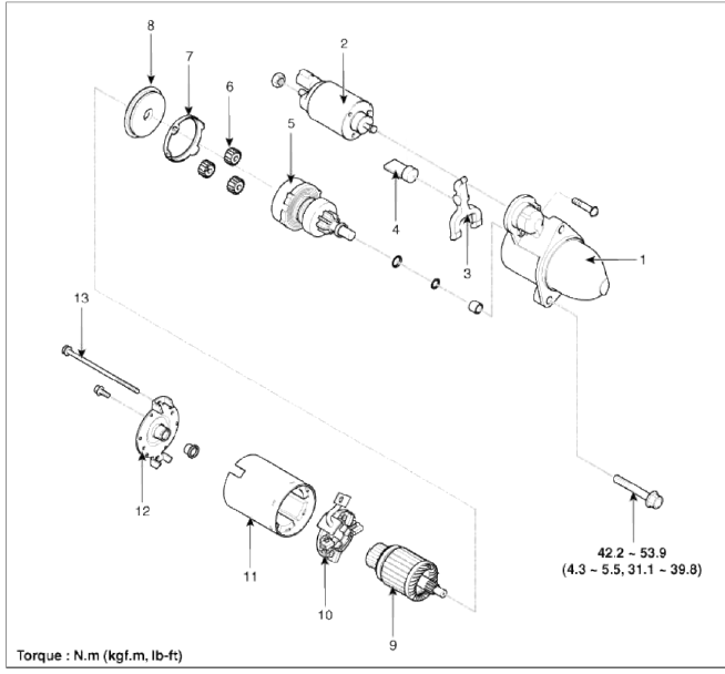
- Front housing
- Starter solenoid assembly
- Lever
- Lever packing
- Planet shaft assembly
- Planetary gear assembly
- Packing
- Shield
- Amature assembly
- Brush holder assembly
- Yoke assembly
- Rear housing
- Through bolt
Repair procedures
Removal and Installation
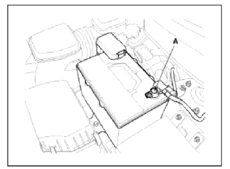
1. Remove the engine cover.
2. Disconnect the battery negative terminal (A).
Tightening torque: 4.0 ~ 6.0N.m (0.4 ~ 0.6kgf.m, 3.0 ~ 4.4lb-ft)
3. Remove the air cleaner assembly. (Refer to EM group)
4. Remove the ETC (Electronic throttle control) module. (Refer to FL group)
5. Remove the intake manifold stay. (Refer to EM group)
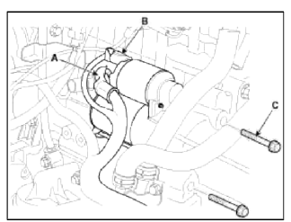
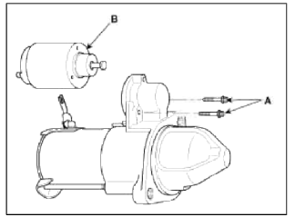
6. Disconnect the starter cable (A) from the Ð’ terminal on the solenoid, then disconnect the connector (B) from the S terminal.
7. Remove the 2 bolts (C) holding the starter, then remove the starter.
Tightening torque: 42.2 ~ 53.9N.m (4.3 ~ 5.5kgf.m, 31.1 ~ 39.8lb-ft)
8. Installation is the reverse of removal.
Disassembly
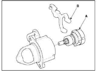
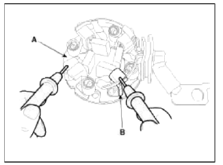
1. Disconnect the M-terminal (A) on the magnet switch assembly (B).
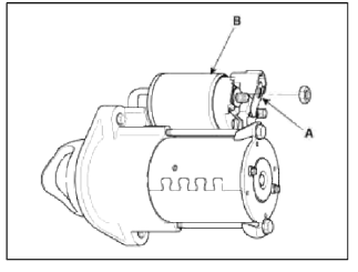
2. After loosening the screws (A), detach the magnet switch assembly (B).
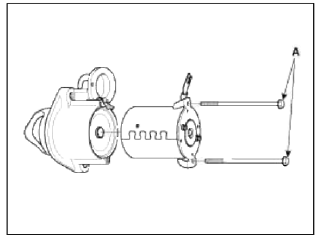
3. Loosen the through bolts (A).
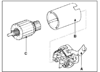
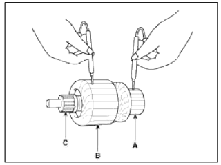
4. Remove the brush holder assembly (A), yoke (B) and armature (C).
5. Remove the lever plate (B) and lever packing (A).
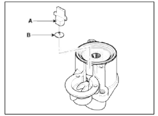
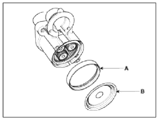
6. Remove the packing (A) and shield (B).
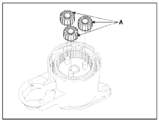
7. Disconnect the planet gear (A).
8. Disconnect the planet shaft assembly (or reducer assembly) (A) and lever (B).
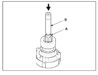
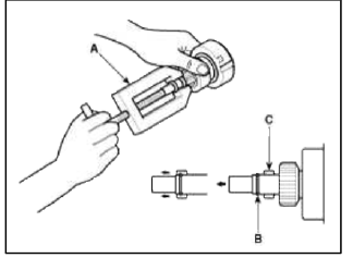
9. Press the stopper (A) using a socket (B).
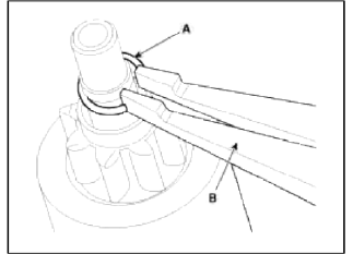
10. After removing the stop ring (A) using stop ring pliers (B).
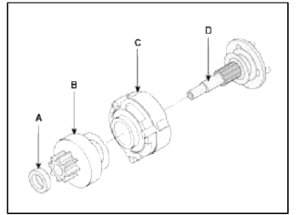
11. Disconnect the stopper (A), overrunning clutch (B), internal gear (C), planet shaft (D) and/or gasket sheet (E).
12. Reassembly is the reverse of disassembly.
Inspection
Armature Inspection And Test
1. Remove the starter.
2. Disassemble the starter as shown at the beginning of this procedure.
3. Inspect the armature for wear or damage from contact with the permanent magnet. If there is wear or damage, replace the armature.
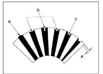
4. Check the commutator (A) surface. If the surface is dirty or burnt, resurface with emery cloth or a lathe within the following specifications, or recondition with #500 or #600 sandpaper (B).
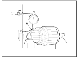
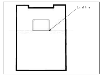
5. Measure the commutator (A) runout.
- If the commutator runout is within the service limit, check the commutator for car bon dust or brass chips between the segments.
- If the commutator run out is not within the service limit, replace the armature.
Commutator runout
Standard (New): 0.02mm (0.0007in.) max
Service limit: 0.05mm (0.0020in.)
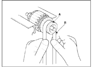
6. Check the mica depth (A). If the mica is too high (B). undercut the mica with a hacksaw blade to the proper depth. Cut away all the mica (C) between the commutator segments. The undercut should not be too shallow, too narrow, or v-shaped (D).
Commutator mica depth
Standard (New): 0.7 ~ 0.9 mm (0.0276 ~ 0.0354 in)
Limit: 0.4 mm (0.0157 in.)
7. Check for continuity between the segments of the commutator. If an open circuit exists between any segments, replace the armature.
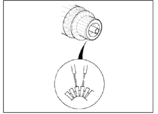
8. Check with an ohmmeter that no continuity exists between the commutator (A) and armature coil core (B), and between the commutator and armature shaft (C). If continuity exists, replace the armature.
Inspect Starter Brush
Blushes that are worm out, or oil-soaked, should be replaced.
Starter Brush Holder Test
Check that there is no continuity between the (-) plate (A) and (+) brush holder (B). If there is continuity, replace the brush holder assembly.
Inspect Overrunning Clutch
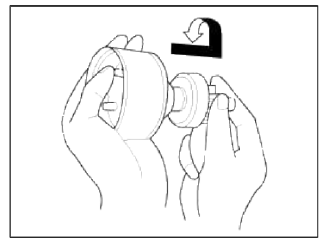
1. Slide the overrunning clutch along the shaft.
Replace it if does not slide smoothly.
2. Rotate the overrunning clutch both ways.
Does it lock in one direction and rotate smoothly in reverse? If it does not lock in either direction or it locks in both directions, replace it.
3. If the starter drive gear is worn or damaged, replace the overrunning clutch assembly, (the gear is not available separately).
Check the condition of the flywheel or torque converter ring gear if the starter drive gear teeth are damaged.
Cleaning
1. Do not immerse parts in cleaning solvent. Immersing the yoke assembly and/or armature will damage the insulation. Wipe these parts with a cloth only.
2. Do not immerse the drive writ in cleaning solvent. The overrun clutch is pre-lubricated at the factory and solvent will wash lubrication from the clutch.
3. The drive unit may be cleaned with a brush moistened with cleaning solvent and wiped dry with a cloth.
READ NEXT:
 Starter Relay
Repair procedures
Inspection
1. Remove the fuse box cover.
2. Remove the starter relay (A).
3. Using an ohmmeter, check that there is continuity between each terminal.
4. Apply 12V to termi
Schematic Diagrams, Description and Operation
Schematic Diagrams
System Block Diagram
Component Parts And Function Outline
* ETS : Electronic Throttle System
Description and Operation
Cruise Control
The cruise control system
SEE MORE:
Operating rear window wiper and washer switch
The rear window wiper and washer
switch is located at the end of the wiper
and washer switch lever.
Turn the switch to the desired position
to operate the rear wiper and washer.
HI - Normal wiper operation
LO - Intermittent wiper operation
OFF - Wiper is not in operation
Pus
Horn
Components and Components Location
Component Location
Horn switch
Horn relay (Engine room
compartment)
Horn (Low pitch)
Clock spring
Repair procedures
Removal
1. Remove the radiator upper cover.
(Refer to the BD group - "Front bumper")
2. Remove the bolt and d
Content
- Home
- Kia Sportage - Fifth generation (NQ5) - (2022-2026) - Owner's Manual
- Kia Sportage - Second generation (JEKM) (2005-2015) - Body Workshop Manual
- Kia Sportage Third generation (SL) - (2011-2016) - Service and Repair Manual
- Sitemap
- Top articles
