Kia Sportage: Direct Electro Hydraulic Actuator Coupling
Description and Operation
Description
4WD ECU processes signals from various sensors and determines the current road and driving conditions. The ECU then utilizes this information to implement precision control over the 4WD coupling's multi-plate clutch and variably adjust the amount of torque delivered to the rear wheels.
Four Wheel Drive (4WD) transfer mode selection
1. AUTO MODE:
- When driving in 4WD AUTO mode, the vehicle operates similar to conventional 2WD vehicles under normal operating conditions. However, if the system determines that there is a need for the 4WD mode, the engine's driving power is distributed to all four wheels automatically without driver intervention.
- When driving on normal roads and pavement, the vehicle moves similar to conventional 2WD vehicles
2. LOCK MODE:
- This mode is used for climbing or descending sharp grades, off-road driving, driving on sandy and muddy roads, etc., to maximize traction.
- This mode automatically begins to deactivate at speeds above 30 km/h (19 mph) and is shifted to 4WD AUTO mode at speed above 40 km h (25 mph). If the vehicle speed decelerates to below 30 km/h (19 mph), however, the transfer mode is shifted into 4WD LOCK mode again.
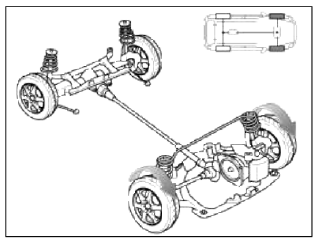
Electronic Coupling - 4WD Control (By Driving Condition)
1. Cruising (Auto Mode)
- Power is delivered mostly to the front wheels.
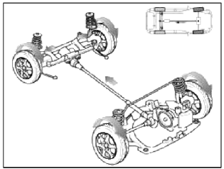
2. Cornering (Auto Mode)
- Adjusts the amount of power to the rear wheels based on the turning radius and cornering speed.
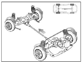
3. Wheel Slip (Auto Mode)
- If one or both of the front wheels lose fraction, the system transfers an appropriate amount of power to the rear wheels based on the slip amount at the front wheels.
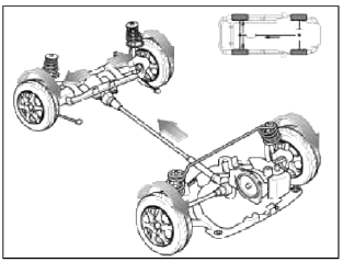
4. Lock Mode
- Maximizes rough terrain performance (active only at speeds below 40 km/h).
Operation
Electronic Coupling
[Inactive]
![[Active]](images/books/1921/1/index%2027.png)
[Active]
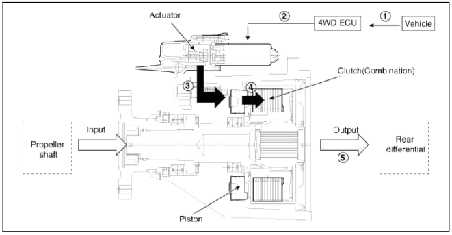
Operation Order
1. 4WD ECU receives CAN signals from the vehicle's sensors.
2. 4WD ECU calculates the necessary amount of rear-wheel torque and sends the corresponding driving current to the actuator (electronic motor and hydraulic pump).
3. Hydraulic pressure generated by the actuator moves the piston.
4. Friction from the piston's movement engages the clutch.
5. Power is delivered to the rear wheels.
Components and Components Location
Component Location
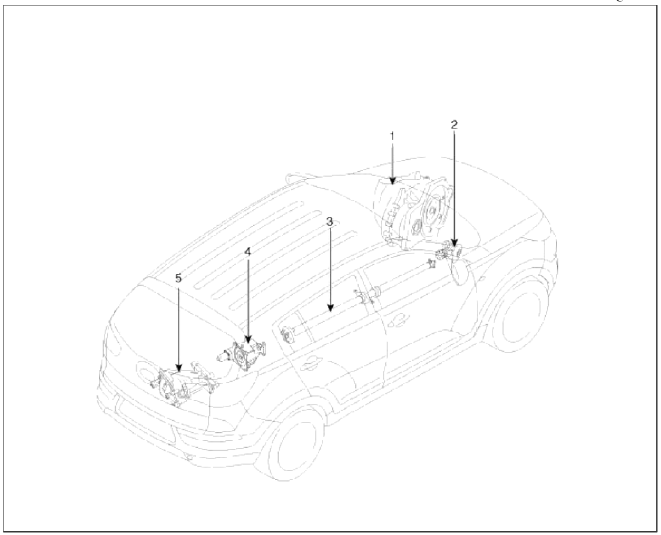
- Automatic transaxle
- Transfer assembly
- Propeller shaft
- Coupling assembly
- Differential assembly
Components
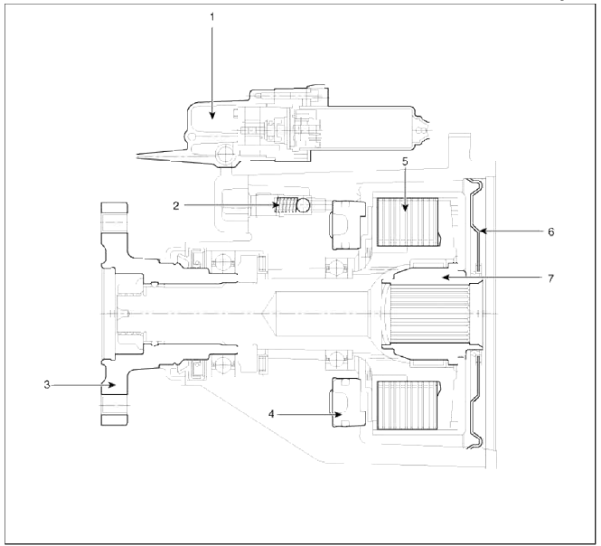
- Actuator
- Bleed valve
- Flange & Input shaft
- Piston
- Clutch pack
- Oil seal cover
- Hub
Repair procedures
Inspection
NOTE
All units are filled up with coupling fluid (ultra-low viscosity ATF) prior to shipping. Inspection, fill-up, and replacement of coupling fluid is therefore not necessary (zero maintenance, lifetime fluid).
Removal
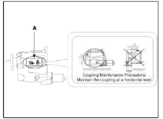
CAUTION
Coupling Maintenance Precautions
Maintain the coupling at a horizontal level.
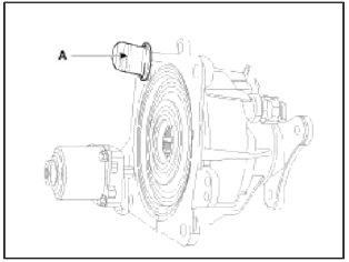
- Refer to the handling caution level (A) when servicing the coupling (removal, installation, replacement, etc.).
- Remove the dipstick and then mount the coupling assembly to the rear differential assembly.
- Maintain the coupling at a horizontal level after removing the dipstick to prevent the fluid from spilling out.
1. Remove the 4WD coupling assembly bolts (A-3ea) mounted to the rear propeller shaft (B).
Tightening torque: 49.0~68.6N.m (5.0~7.0kgf.m, 36.2~50.6lb-ft)
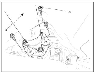
2. Using a flat tool, separate the propeller shaft from 4WD coupling assembly.
3. Remove the electric magnetic clutch connector (A).
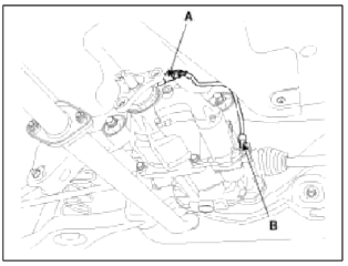
4. Remove the 4WD coupling assembly mounting bolts (A-4ea).
Tightening torque: 58.8~63.7N.m (6.0~6.5kgf.m, 43.4~47.0lb-ft)
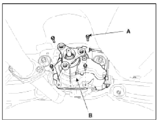
5. Using a flat tool, separate the 4WD coupling assembly from the rear differential carrier assembly.
Installation
1. Installation is the reverse of removal.
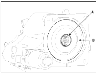
NOTE
- Grease the spline hole (A) of the coupling assembly.
Grease
Extreme Pressure (EP) grease containing molybdenum disulfide (MoS2)
- When installation the coupling, be careful not to damage the oil seal (B).
CAUTION
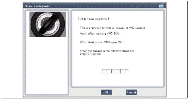
After replacing the coupling, reset the 4WD ECU's clutch learing using the GDS tool. (Refer to "Coupling assembly" in 4WD group).
Adjustment
Description
The friction material inside the coupling will degrade over time. Therefore, corresponding compensation values must be referenced and entered after replacing the controller or the coupling.
Compensation Requirement and Procedure
1. Simultaneous replacement of 4WD ECU (Controller) and coupling
- Does not require compensation.
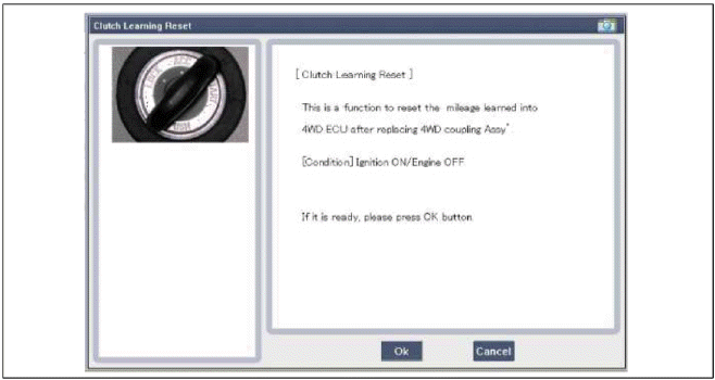
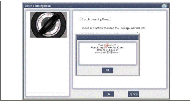
2. Replacement of coupling only
- Reset the 4WD ECU's (Controller) clutch learing.
3. Replacement of 4WD ECU (Controller) only
- Before replacement: Check the ECU's clutch tearing.
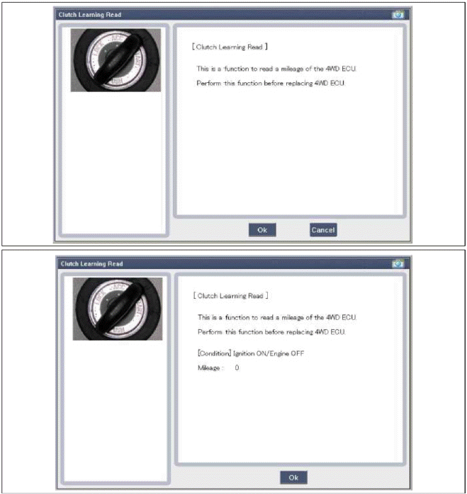
- After replacement: Enter the original ECU's clutch tearing into the replacement ECU.
READ NEXT:
 Oil hydraulic Motor (Actuator)
Description and Operation
Description
The 4WD ECM controls the Pump Motor Pump (Actuator) to generating an oil
pressure. The pressure engages a multiple
disk clutch to transfer torque to th
Pressure Sensor
Description and Operation
Description
The 4WD ECU makes a Motor Pump (Actuator) turn round for generating an oil
pressure. And then it presses a multiple
disk clutch and transfers the gener
SEE MORE:
Snowy or icy conditions
Severe weather conditions in the winter
result in greater wear and other problems.
To minimize the problems of winter driving,
you should follow these suggestions:
Snowy or icy conditions
To drive your vehicle in deep snow, it
may be necessary to use snow tires or to
install tire chains on
Surround View Monitor settings
Surround View Monitor can assist in
parking by allowing the driver to see
around the vehicle.
Detecting sensor
1: SVM-front view camera
2, 3: SVM-side view camera (under the
side view mirror)
4: SVM-rear view camera
Refer to the picture above for the
detailed location of
Content
- Home
- Kia Sportage - Fifth generation (NQ5) - (2022-2026) - Owner's Manual
- Kia Sportage - Second generation (JEKM) (2005-2015) - Body Workshop Manual
- Kia Sportage Third generation (SL) - (2011-2016) - Service and Repair Manual
- Sitemap
- Top articles
