Kia Sportage: Oil hydraulic Motor (Actuator)
Description and Operation
Description
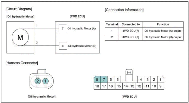
The 4WD ECM controls the Pump Motor Pump (Actuator) to generating an oil pressure. The pressure engages a multiple disk clutch to transfer torque to the rear wheels. The torque to the rear wheels varies according to the pressure on the clutch.
Schematic Diagrams
Circuit Diagram
Repair procedures
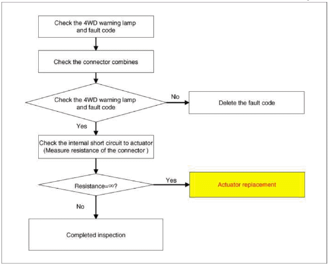
Inspection
NOTE
If you have trouble code related to the oil hydraulic motor (actuator) (P1825, P1826, P1827, P1828), check oil hydraulic motor (actuator) according to the inspection process.
Oil Hydraulic Motor (Actuator) Inspection Procedure
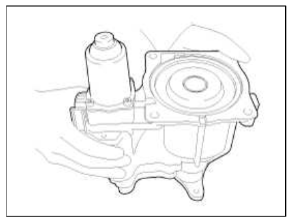
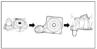
Removal
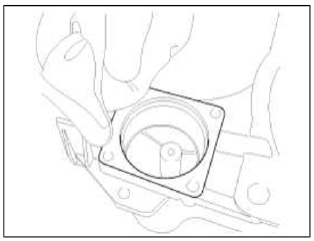
1. Remove the coupling assembly. (Refer to "coupling assembly" in 4WD group).
2. Keep going perpendicular state after remove the coupling assembly.
NOTE
- Keep going perpendicular state during remove (install) the hydraulic motor (actuators).
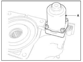
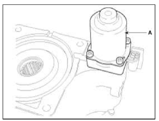
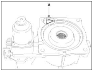
3. Remove the hydraulic motor (actuators) after loosening bolts with hex wench.
CAUTION
- Remove the hydraulic motor (actuators) after dropping residual oil as much as possible inside the coupling. (abut 5-10 sec)
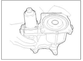
Installation
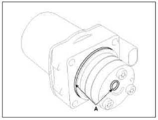
1. Before installation, wipe the surface with a clean cloth.
2. Check the О-rings of the new hydraulic motor (actuators).
CAUTION
- You have to prevent any dust from entering inside hydraulic motors (actuators) and housing.
3. Tighten the bolts after install the hydraulic motor (actuators).
CAUTION
- When installing, motor connector has to toward in the direction of outside of the Coupling.
Tightening torque: 8.8 ~ 10.8 N.m (0.9 ~ 1.1 kgf.m, 6.5 ~ 8.0 lb-ft)
NOTE
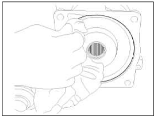
- When installing, oil can be reflux by the pressure in aft breather hole. (Oil reflux weight: about 5 ~ 10 ml)
- Change direction in the direction of the arrow and lay on the floor
as shown in the illustration.
The reflux oil will flow to the bottom.
- You have to prevent additional backflow in according to order as shown in the illustration.
4. Wipe the flowed oil to around the surface with a clean cloth.
5. Measure the weight of the coupling.
Coupling assembly weight: 8.18 ~ 8.23kg (Current oil capacity 490ml)
CAUTION
- If the weight of the coupling assembly is less than 8.18kg, must be replace the coupling assembly because of suspect excessive reflux.
READ NEXT:
 Pressure Sensor
Description and Operation
Description
The 4WD ECU makes a Motor Pump (Actuator) turn round for generating an oil
pressure. And then it presses a multiple
disk clutch and transfers the gener
General Information
Specifications
Specifications
VFS: Variable Force Solenoid
Sensors
Input Speed Sensor
Type: Hall effect sensor
Specifications
Output Speed Sensor
Type: Hall effe
SEE MORE:
Front Disc Brake
Components and Components Location
Components
Guide rod bolt
Bleed screw
Caliper bracket
Caliper body
Inner pad shim
Brake pad
Pad retainer
Repair procedures
Removal
1. Remove the front wheel & tire.
Tightening torque:
88.3 ~ 107.9 N.m (9.0 ~ 11.0 kgf.m, 65.1 ~ 79
Folding the rear seat
The rear seatbacks may be folded to
facilitate carrying long items or to
increase the luggage capacity of the
vehicle.
WARNING
Folded Seatback
The purpose of the fold-down rear seatbacks
is to allow you to carry longer
objects that could not otherwise be
accommodated.
Never allow a pass
Content
- Home
- Kia Sportage - Fifth generation (NQ5) - (2022-2026) - Owner's Manual
- Kia Sportage - Second generation (JEKM) (2005-2015) - Body Workshop Manual
- Kia Sportage Third generation (SL) - (2011-2016) - Service and Repair Manual
- Sitemap
- Top articles
