Kia Sportage: Exhaust Manifold
Components and Components Location
Components
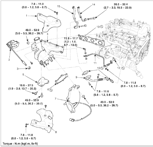
- Hear protector
- EWGA (Electric Waste Gate Actuator)
- C-ring
- Turbo manifold module
- Turbocharger stay
- Turbo adapter gasket
- Turbo adapter
- Turbo adapter heat protector
- Oil drain pipe assembly
- Turbocharger oil drain gasket
- Oil feed pipe & hose assembly
- Oil drain gasket
- Exhaust manifold gasket
- Turbocharger water feed hose
- Turbocharger water drain hose
Repair procedures
Removal and Installation
1. Remove the engine cover.
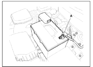
2. Disconnect the battery negative terminal (A).
Tightening torque
4.0 ~ 6.0N.m (0.4 ~ 0.6kgf.m, 3.0 ~ 4.4lb-ft)
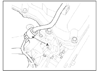
3. Disconnect the oxygen sensor connector (A).
4. Remove the exhaust manifold heat protectors (A).
Tightening torque: 7.8 ~ 11.8N.m (0.8 ~ 1.2kgf.m, 5.8 ~ 8.7lb-ft)
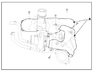
CAUTION
Check that engine is cool enough to work.
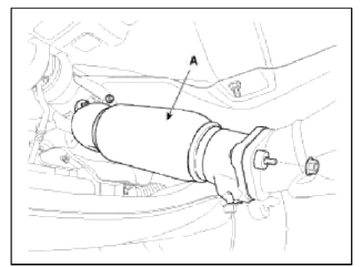
5. Remove the front muffler (A).
Tightening torque: 39.2 ~ 58.8 N.m (4.0 ~ 6.0 kgf.m, 28.9 ~ 43.4 lb-ft)
6. Support the sub frame (A) with a floor jack, and then remove the sub frame mounting bolts and nuts.
Tightening torque: 176.5 ~ 196.1 N.m (18.0 ~ 20.0 kgf.m, 130.2 ~ 144.7 lb-ft)
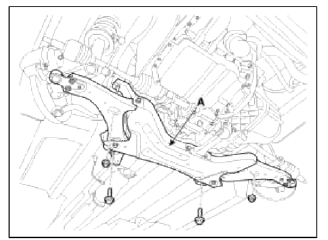
NOTE
- After removing the sub frame mounting bolt, the engine and transaxle assembly may fall downward, and so support them securely with floor jack.
- Verify that the hoses and connectors are disconnected before removing the engine and transaxle assembly.
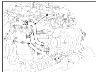
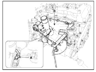
7. Disconnect the turbocharger water feed hose (A) and the water drain hose (B).
8. Remove the turbocharger stay (A) and then disconnect the oil drain pipe (B) and gasket.
Tightening torque:
Bolts (C): 18.6 ~ 27.5N.m (1.9 ~ 2.8kgf.m, 13.7 ~ 20.3lb-ft)
Bolts (D ): 49.0 ~ 53.9N.m (5.0 ~ 5.5kgf.m, 36.2 ~ 39.8lb-ft)
Bolts (E ): 7.8 ~ 11.8N.m (0.8 ~ 1.2kgf.m, 5.8 ~ 8.7lb-ft)
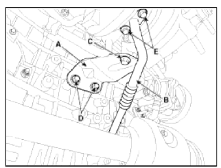
NOTE
When installing, clean the gasket surface and replace the oil drain pipe gasket with new one.
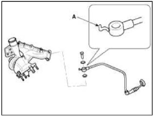
9. Disconnect the oil feed pipe (A) and then remove the turbo manifold module (B).
Tightening torque
Oil feed pipe eye bolt: 11.8 ~ 17.7N.m (1.2 ~ 1.8kgf.m, 8.7 ~ 13.0lb-ft)
Turbo manifold module nuts: 49.0 ~ 53.9N.m (5.0 ~ 5.5kgf.m, 36.2 ~ 39.7lb-ft)
CAUTION
When installing the oil feed pipe & hose, make sure the stopper (A) don't touch the compressor housing.
Be careful not to bend or crush the pipe & hose.
NOTE
When installing, be sure the eye bolt о-rings are completely seated in both hole of oil feed pipe.
NOTE
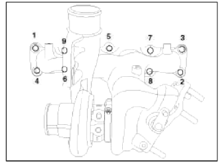
When installing, replace with a new gasket.
When installing the turbo manifold module, tighten the nuts with pre-torque first, and then tighten the nuts with specified torque in the sequence shown.
10. Remove the turbo manifold module gasket (A).
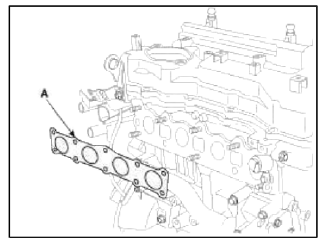
11. Installation is reverse order of removal.
NOTE
- Always use the new turbo manifold module and turbo adapter gaskets when replacing.
- Always use a new turbocharger nuts and, exhaust manifold nuts when it is removed.
- Take care whether the oil feed pipe & hose assembly is interfered with turbo manifold module and any surrounding parts.
- If the oil feed pipe & hose is damaged, engine oil is not supplied sufficiently to the turbocharger then it may damage the turbocharger. If the oil drain pipe & hose is damaged and clogged, engine oil is not drained smoothly then it may cause oil leaks from the turbocharger. Be care fill the oil feed pipe & hose not to damage. (bent, crushed, tom or cracked).
READ NEXT:
 Turbo Charger
Components and
Components Location
Components
Turbine housing
Turbine inlet
Turbine outlet
Compressor housing
Compressor inlet
Compressor outlet
Center housing
EWGA (Electr
Intercooler
Components and
Components Location
Components
Recirculation hose
Intercooler inlet hose & pipe
assembly
Intercooler outlet hose & pipe
assembly
Intercooler mounting bra
Muffler
Components and Components
Location
Components
Front muffler
Catalytic converter
Center muffler
Main muffler
Gasket
Repair procedures
Removal and Installation
1. Remove the f
SEE MORE:
Automatic-Dimming Night Vision
Safety (NVS) Mirror (if
equipped)
The NVS Mirror automatically reduces
glare by monitoring light levels in the
front and the rear of the vehicle. Any
objects that obstructs the light sensor
will degrade the automatic dimming
control feature.
For more information regarding NVS
mirrors and other applications, please
refer to t
Front Bumper | Rear Bumper
Components and Components Location
Components
Front bumper cover
Front bumper side bracket [LH]
Front bumper side bracket [RH]
Repair procedures
Replacement
CAUTION
Put on gloves to protect your hands.
Use a plastic panel removal tool to remove inter
Content
- Home
- Kia Sportage - Fifth generation (NQ5) - (2022-2026) - Owner's Manual
- Kia Sportage - Second generation (JEKM) (2005-2015) - Body Workshop Manual
- Kia Sportage Third generation (SL) - (2011-2016) - Service and Repair Manual
- Sitemap
- Top articles
