Kia Sportage: Intercooler
Components and Components Location
Components
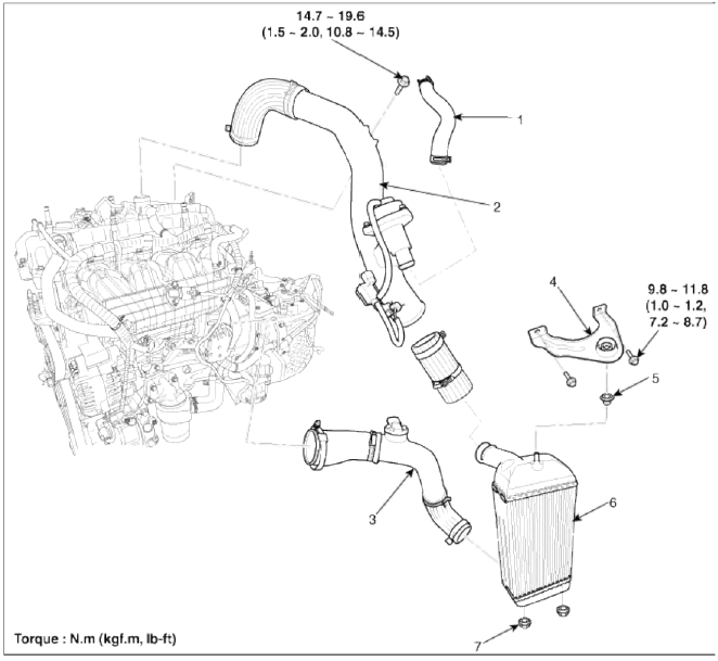
- Recirculation hose
- Intercooler inlet hose & pipe assembly
- Intercooler outlet hose & pipe assembly
- Intercooler mounting bracket
- Intercooler upper mounting insulator
- Intercooler
- Intercooler lower mounting insulator
Repair procedures
Removal and Installation
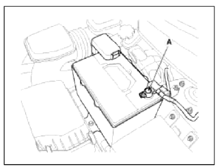
1. Disconnect the battery negative terminal (A).
Tightening torque 4.0 ~ 6.0N.m (0.4 ~ 0.6kgf.m, 3.0 ~ 4.4lb-ft)
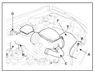
2. Remove the air cleaner assembly.
- Remove the air duct (A).
- Disconnect the breather hose (B), the recirculation hose (C) and the brake booster vacuum hose (D).
- Disconnect the air intake hose (E) and then remove the air cleaner assembly (F).
Tightening torque
Hose clamp bolt: 2.9 ~ 4.9N.m (0.3 ~ 0.5kgf.m, 2.2 ~ 3.6lb-ft)
Air cleaner assembly bolts: 7.8 ~ 9.8N.m (0.8 ~ l.0kgf.m, 5.8 ~ 7.2lb-ft)
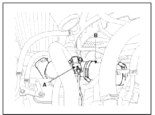
3. Disconnect the recirculation valve connector (A) and the vacuum hose (B), and then remove the intercooler inlet pipe assembly (C).
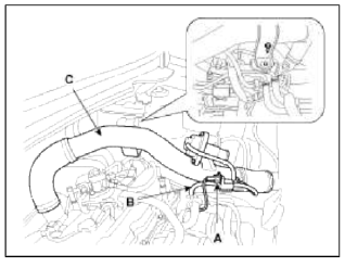
4. Disconnect the boost pressure sensor connector (A) and then remove the intercooler outlet pipe & hose assembly (B).
Tightening torque 4.9 ~ 6.9 N.m (0.5 ~ 0.7 kgf.m 3.6 ~ 5.1 lb-ft)
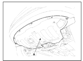
5. Remove the under cover (A).
Tightening torque: 9.8 ~ 11.8 N.m (1.0 ~ 1.2 kgf.m, 7.2 ~ 8.7 lb-ft)
6. Remove the front bumper. (Refer to BD group)
7. Remove the front bumper upper stiffner (A).
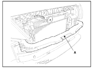
8. Remove the radiator upper cover (A).
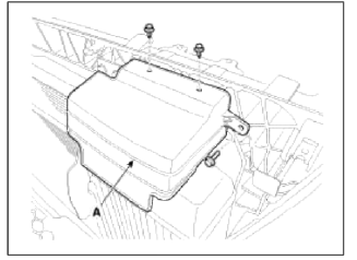
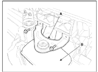
9. Remove the intercooler upper mounting bracket (A) and then remove the intercooler (B).
Tightening torque 9.8 ~ 11.8 N.m (1.0 ~ 1.2 kgf.m, 7.2 ~ 8.7 lb-ft)
10. Installation is reverse order of removal.
READ NEXT:
 Muffler
Components and Components
Location
Components
Front muffler
Catalytic converter
Center muffler
Main muffler
Gasket
Repair procedures
Removal and Installation
1. Remove the f
SEE MORE:
Cruise Control (CC)
Cruise Control (CC) (if equipped)
Cruise indicator
Set speed
Cruise Control will allow you to drive at
speeds above 20 mph (30 km/h) without
depressing the accelerator pedal.
Cruise Control operation
To set speed
Accelerate to the desired speed,
which must be more than 20 mph
Oil hydraulic Motor (Actuator)
Description and Operation
Description
The 4WD ECM controls the Pump Motor Pump (Actuator) to generating an oil
pressure. The pressure engages a multiple
disk clutch to transfer torque to the rear wheels. The torque to the rear
wheels varies according to the pressure on the
clutch.
S
Content
- Home
- Kia Sportage - Fifth generation (NQ5) - (2022-2026) - Owner's Manual
- Kia Sportage - Second generation (JEKM) (2005-2015) - Body Workshop Manual
- Kia Sportage Third generation (SL) - (2011-2016) - Service and Repair Manual
- Sitemap
- Top articles
