Kia Sportage: Side Body | Interior
Body Repair
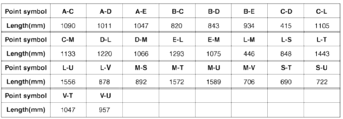
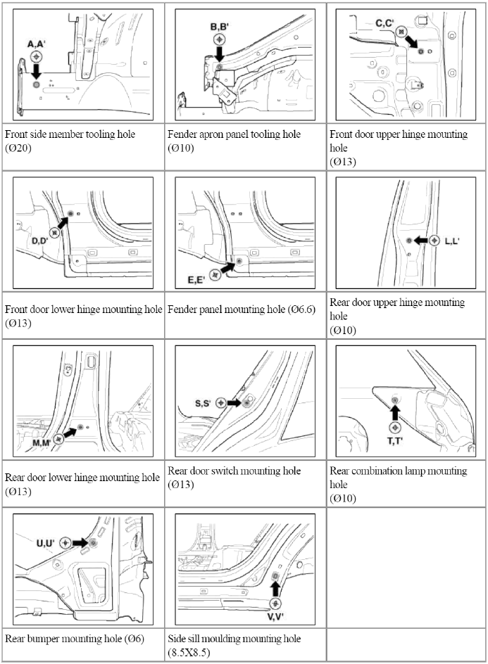
Side Body A
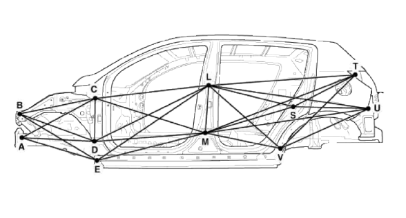
* These dimensions indicated in this figure are actual-measurement dimensions.
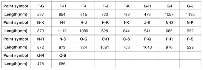
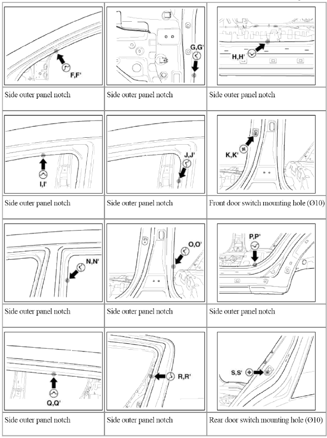
Side Body Ð’
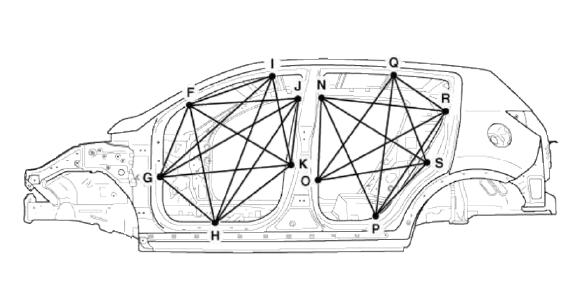
* These dimensions indicated in this figure are actual-measurement dimensions.
Interior
Body Repair
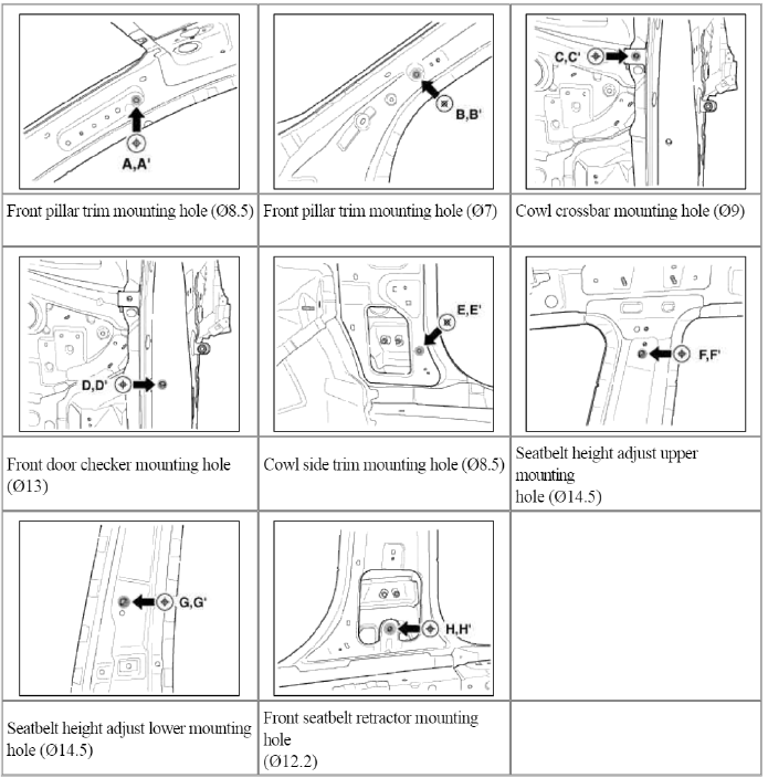
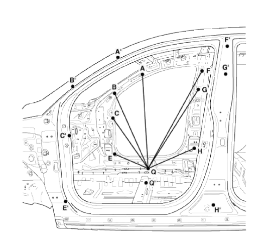
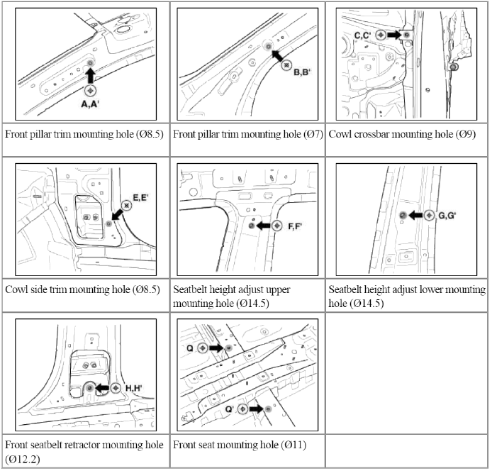
Interior A
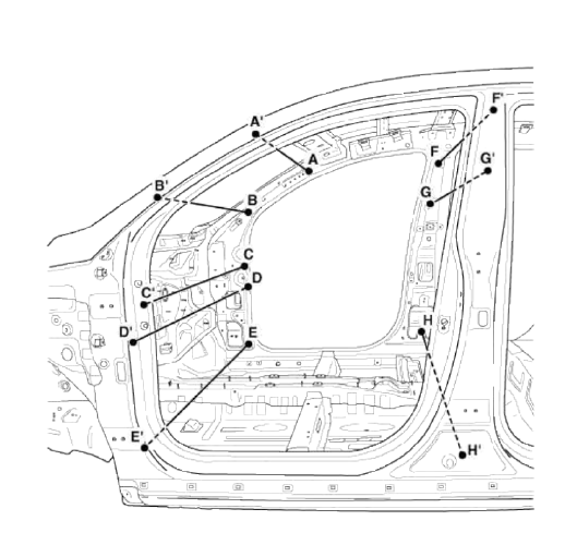
* These dimensions indicated in this figure are actual-measurement dimensions.

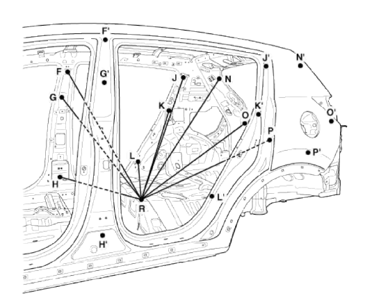
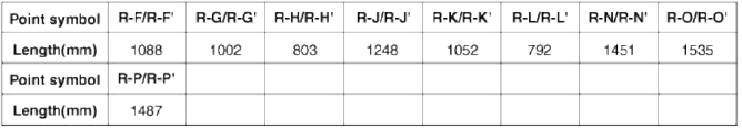
Interior Ð’
* These dimensions indicated in this figure are actual-measurement dimensions.
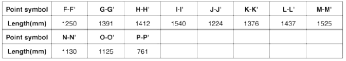
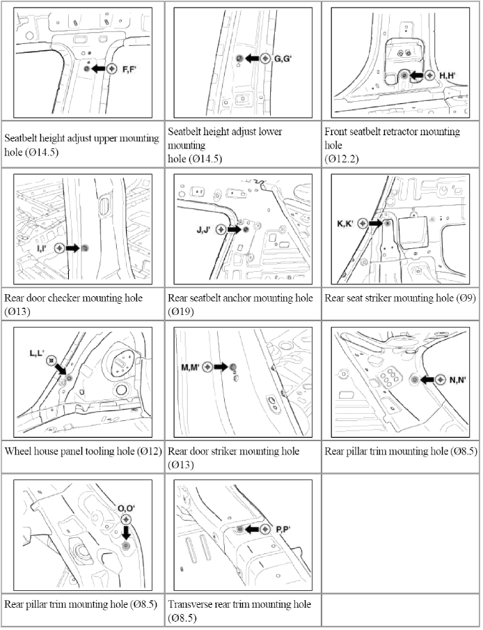
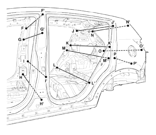
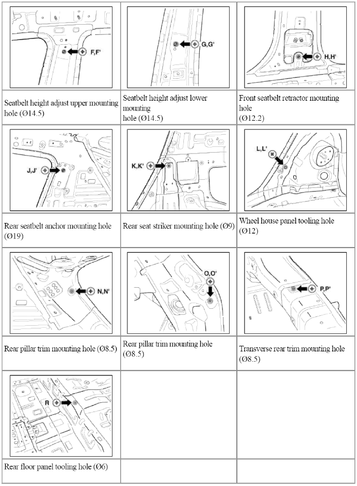
Interior C
* These dimensions indicated in this figure are actual-measurement dimensions.

Interior D
* These dimensions indicated in this figure are actual-measurement dimensions.
READ NEXT:
 Rear Body, Under Body
Rear Body
Body Repair
* These dimensions indicated in this figure are actual-measurement
dimensions.
Under Body
Body Repair
Projected Dimensions
* These dimensions indicated in t
SEE MORE:
Repair procedures
Inspection
Self Diagnosis With Scan Tool
Smart key system defects can be quickly diagnosed with the GDS. GDS operates
actuator quickly to monitor,
input/output value and self diagnosis.
The following three features will be major problem in SMART KEY system.
1. Problem in SMART KEY unit
Refrigerant line | Compressor
Components and Components Location
Component Location
Repair procedures
Replacement
1. Discharge refrigerant from refrigeration system.
2. Replace faulty tube or hose.
CAUTION
Cap the open fittings immediately to keep moisture or dirt out of the system.
3. Tighten joint of bolt or nu
Content
- Home
- Kia Sportage - Fifth generation (NQ5) - (2022-2026) - Owner's Manual
- Kia Sportage - Second generation (JEKM) (2005-2015) - Body Workshop Manual
- Kia Sportage Third generation (SL) - (2011-2016) - Service and Repair Manual
- Sitemap
- Top articles
