Kia Sportage: Inhibitor Switch
Description and Operation
Description
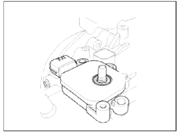
Inhibitor Switch monitors the lever's position (PRXD) and is used to control gear setting signals.
Specifications
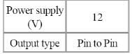
Specifications
Type: Combination of output signals from 4 terminals
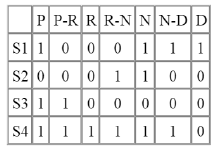
Signal Code Table
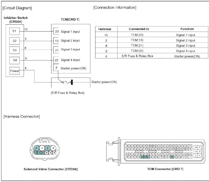
Schematic Diagrams
Circuit Diagram
Repair procedures
Removal
1. Make sure vehicle does not roll before setting room side shift lever and T/M side manual control lever to "N" position.
2. Remove the battery and the battery tray. (Refer to "Charging system" in EE group.)
3. Remove the air cleaner assembly. (Refer to "Intake manifold" in EM group.)
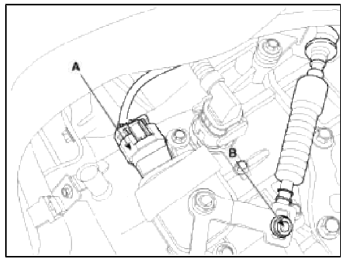
4. Remove the shift cable mounting nut (B).
Tightening torque: 7.8 ~ 11.8 N.m (0.8 ~ 1.2 kgf.m, 5.7 ~ 8.6 lb-ft)
5. Disconnect the inhibitor switch connector (A).
6. Remove the manual control lever (A) and the washer (B) after removing a nut (C).
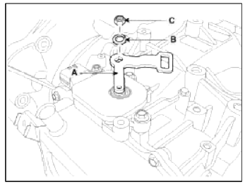
CAUTION
When installing, affix the manual control lever and the inhibitor switch with Ø5mm (0.1969in.). Then tighten the inhibitor assembly mounting bolts.
7. Remove the inhibitor assembly (A) after removing the bolts (2ea).
Tightening torque: 9.8 ~ 11.8 N.m (1.0 ~ 1.2 kgf.m, 7.2 ~ 8.7 lb-ft)
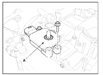
CAUTION
When installing, tighten the inhibitor assembly mounting bolt lightly, so that necessary adjustments can be made. Tighten to specifications.
Installation
1. Installation is the reverse of removal.
READ NEXT:
 Shift Lever
Components and Components Location
Components
Shift lever knob & boots
assembly
Shift lever assembly
Control cable assembly
Manual control lever (T/M side)
Repair procedure
General Information
Specifications
Specifications
Tightening Torque
Special Service Tools
Special Tools
Troubleshooting
Troubleshooting
SEE MORE:
Luggage room lamp
: The lamp will always turn
on
when the liftgate is opened/closed.
: The lamp is on when the
liftgate
is opened, and off when the liftgate is
closed.
: The lamp will always turn
off
when the liftgate is opened/closed.
The luggage room lamp comes on when
the liftgate i
Balance Shaft & Oil Pump
Components and
Components Location
Components
Balance shaft & oil pump
assembly
Balance shaft chain tensioner
Balance shaft chain
Balance shaft chain sprocket
Balance shaft chain guide
Balance shaft chain tensioner arm
Oil cooler
Oil filter
Repair procedures
Rem
Content
- Home
- Kia Sportage - Fifth generation (NQ5) - (2022-2026) - Owner's Manual
- Kia Sportage - Second generation (JEKM) (2005-2015) - Body Workshop Manual
- Kia Sportage Third generation (SL) - (2011-2016) - Service and Repair Manual
- Sitemap
- Top articles
