Kia Sportage: Mode Control Actuator
Components and Components Location
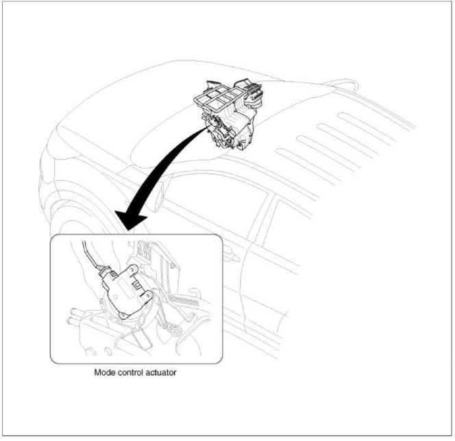
Component Location
Description and Operation
Description
The mode control actuator is located at the heater unit.
It adjusts position of mode door by operating mode control actuator based on signal of Ð/С control unit. Pressing mode select switch makes the mode control actuator shift in order of vent → B/L → floor → mix.
Repair procedures
Inspection
1. Ignition "OFF".
2. Disconnect the connector of mode control actuator.
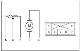
3. Verify that the mode control actuator operates to the defrost mode when connecting 12V to the terminal 3 and grounding terminal 4.
4. Verify that the mode control actuator operates to the vent mode when connecting in the reverse.
- -
- -
- Defrost mode
- Vent mode
- Sensor ground
- Feedback signal
- 5V (Vcc)
5. Check the voltage between terminals 5 and 6.
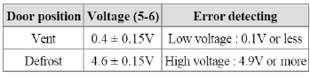
It will feedback current position of actuator to controls.
6. If the measured voltage is not specification, substitute with a known-good mode control actuator and check for proper operation.
7. If the problem is corrected, replace the mode control actuator.
Replacement
1. Disconnect the negative (-) battery terminal.
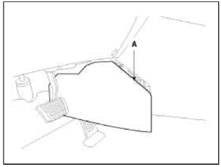
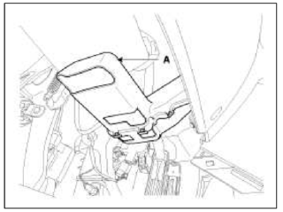
2. Remove the crash pad left side cover (A).
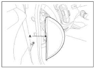
3. Remove the left extension cover (A).
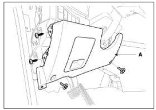
4. Remove the crash pad lower cover (A).
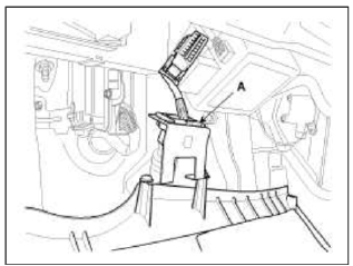
5. Disconnect the diagnosis connector (A).
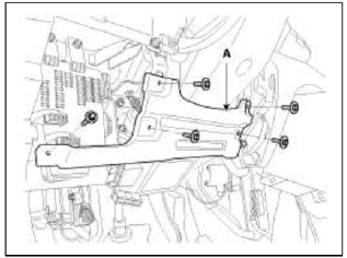
6. Remove the reinforcing panel (A).
7. Remove the left shower duct (A).
8. Remove the BCM.
(Refer to BE group - "BCM")
9. Disconnect the mode control actuator connector (A).
10. Loosen the mounting screw and then remove the mode control actuator (B).
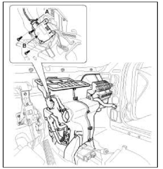
11. Installation is the reverse order of removal.
READ NEXT:
 Blower Unit | Blower Motor
Components and Components Location
Component Location
Components
Intake case (LH)
Intake case (RH)
Blower motor
Intake door
Intake actuator
Mofet [Aut
SEE MORE:
Smart key unit
Components and Components Location
Components
Connector Pin Information
Connector A (14 Pin)
Ground 1
A_ACC
A_IGN2
A_IGN1
VBAT_CPU
VBAT_LOAD
Ground 2
-
O_Exterior buzzer
O_ACC Relay
O_IGN1 Relay
O_IGN2 Relay
O_Starter Relay
-
Connector Ð’ (26 Pin)
-
Cylinder Head | Removal - Repair procedures - Cylinder Head
Components and Components Location
Components
Camshaft bearing cap
Camshaft front bearing cap
Exhaust camshaft
Intake camshaft
Exhaust CVVT assembly
Intake CVVT assembly
Exhaust camshaft upper bearing
Exhaust camshaft lower bearing
MLA
Ret
Content
- Home
- Kia Sportage - Fifth generation (NQ5) - (2022-2026) - Owner's Manual
- Kia Sportage - Second generation (JEKM) (2005-2015) - Body Workshop Manual
- Kia Sportage Third generation (SL) - (2011-2016) - Service and Repair Manual
- Sitemap
- Top articles
